Light source device and projector

a light source device and projector technology, applied in lighting and heating apparatus, process and machine control, instruments, etc., can solve the problems of reducing the light-focusing efficiency of an optical system, reducing by degrees the brightness of images, and prolonging the arc length being the distance between the electrodes, so as to achieve less brightness reduction and long life cycle

Inactive Publication Date: 2008-08-14
SEIKO EPSON CORP
View PDF4 Cites 18 Cited by
  • Summary
  • Abstract
  • Description
  • Claims
  • Application Information

AI Technical Summary

Benefits of technology

[0006]An advantage of some aspects of the invention is to provide a light source device that is long in life cycle with less brightness reduction even if the device is used for a long time, and a projector equipped with such a light source device.

Problems solved by technology

If the light source device of such a configuration is used for a long time, the electrodes of the arc tube are deteriorated, thereby lengthening the arc length being the distance between the electrodes.
This resultantly reduces the light-focusing efficiency in an optical system, thereby causing a problem of reducing by degrees the brightness of images.
There is also a problem of degrading the brightness due to devitrification or others, which is caused by the silica glass configuring the arc tube being exposed to the high temperature.
Therefore, it is indeed capable of increasing the brightness for the time being, but instead accelerates the deterioration of the electrodes, thereby failing to increase the life cycle of the light source device.
With such a decrease of power, the electrodes do not suffer from the heat load that much, and thus this favorably delays the progress of deterioration of the electrodes as a result of the long-time use of the light source device.

Method used


Image

  • Light source device and projector
  • Light source device and projector
  • Light source device and projector

Examples


first embodiment

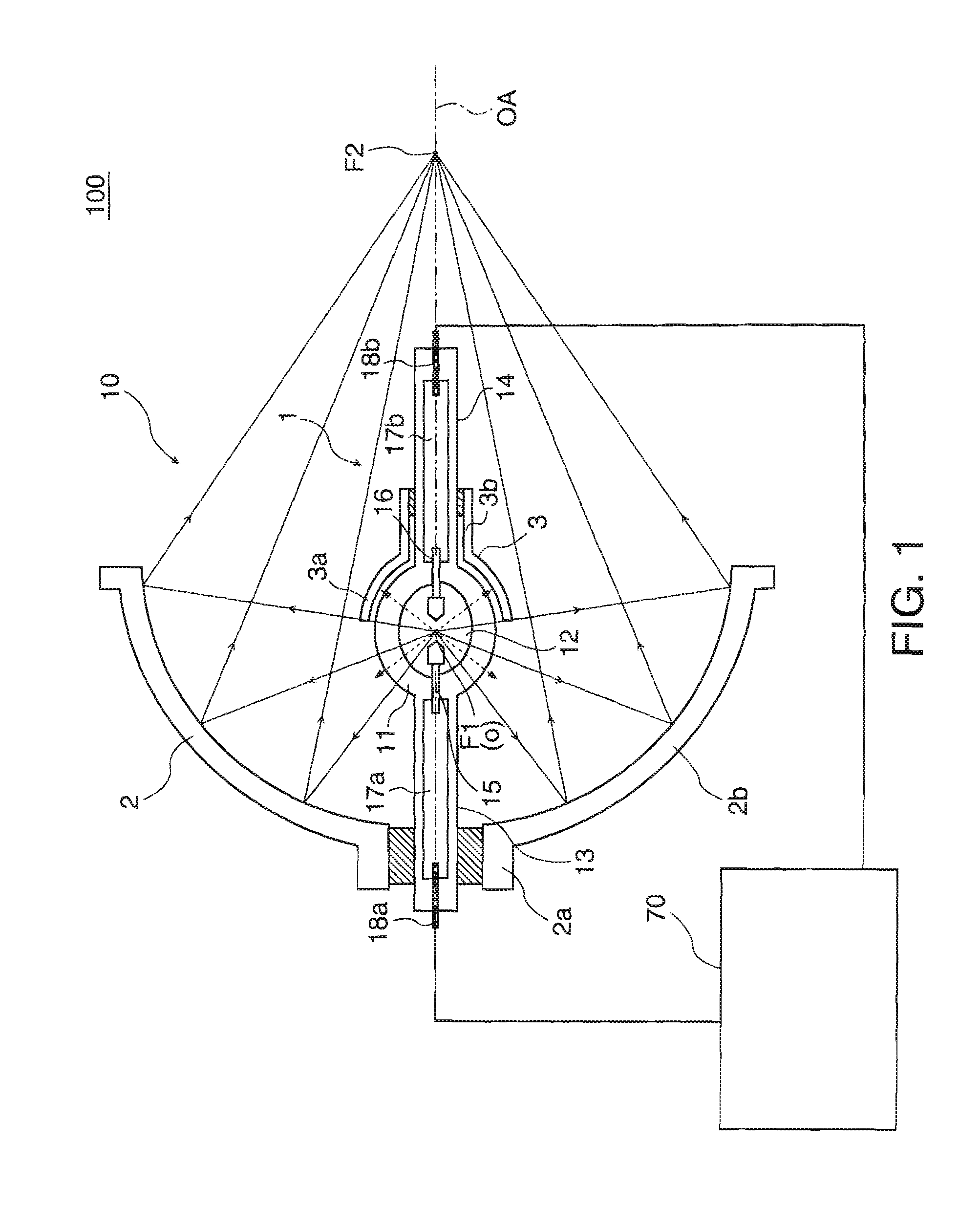
[0026]FIG. 1 is a cross sectional diagram for illustrating the configuration of a light source device of a first embodiment. A light source device 100 of the embodiment is configured to include a light source unit 10, and a light source drive device 70 corresponding to a drive control section. The light source unit 10 is configured to include an arc tube 1 of discharge emission type, a reflector 2 serving as an elliptic-shaped main reflector, and a sub-mirror 3 serving as a spherical sub reflector.

[0027]The arc tube 1 is configured by a light-transmissive silica-glass-made tube whose center portion is bulged like a sphere. The arc tube is configured to include a main portion 11 that emits lights for illumination use, and first and second sealing portions 13 and 14 that respectively extend to both end sides of the main portion 11.

[0028]The main portion 11 includes therein a discharge space 12, in which tungsten-made first and second electrodes 15 and 16 are disposed with a predetermi...

second embodiment

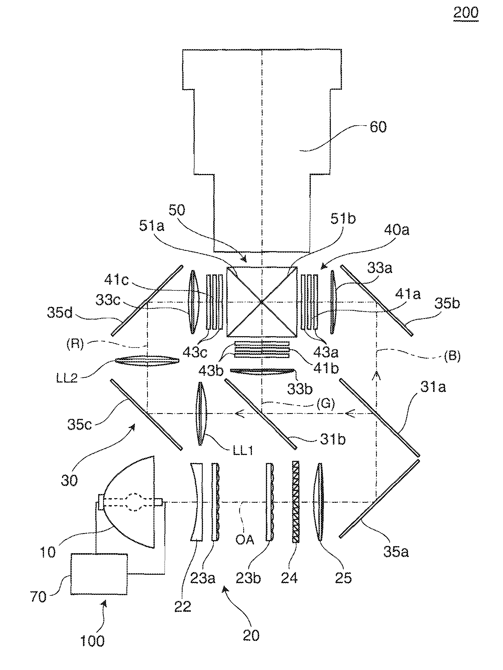
[0054]FIG. 9 is a conceptual view for illustrating the configuration of an optical system in a projector equipped with the light source device of the first embodiment. This projector 200 is configured to include the light source device 100 of FIG. 1, an illumination system 20, a color separation system 30, a light modulation section 40, a cross dichroic prism 50, and a projection lens 60, all of which are disposed in order along the optical axis OA. The illumination system 20 serves to make source lights uniform before emission, and the color separation system 30 divides the light sources coming from the illumination system 20 into three colors of red, green, and blue. The light modulation section 40 is illuminated by the source lights of various colors coming from the color separation system 30, arid the cross dichroic prism 50 combines image lights of various colors coming from the light modulation section 40. The projection lens 60 is a projection system for use to project the im...


PUM


Abstract

A light source device includes: a light source unit including an arc tube that emits a light between a pair of electrodes, and a reflector that reflects the light coming from the arc tube for emission of a source light; and a drive control section that drives the light source unit by a predetermined driving power. In the device, the drive control section performs power regulation control of reducing the driving power of the light source unit at a predetermined timing by a predetermined amount.

Description

BACKGROUND[0001]1. Technical Field[0002]The present invention relates to a light source device, and a projector using the light source device.[0003]2. Related Art[0004]The previously known projector is of a type forming an image through modulation of a source light coming from a light source, and emitting the resulting image onto a screen or others. The previously known projector is also of a type changing a driving voltage of a light source device, i.e., lamp. As an example, Patent Document 1 (JP-A-2000-131760) describes a projector of performing control of increasing the driving voltage of a lamp at a time point when the amount of light emission of the lamp reaches a predetermined value lower than an intermediate value between the initial amount of light emission and the amount of light emission of the lamp coming close to the end of its life cycle. With this technology, images to be projected on a screen can be kept bright without shortening the life cycle of the lamp while suppr...

Claims


Application Information

Patent Timeline
Patent Type & Authority Applications(United States)
IPC IPC(8): G03B21/20H05B41/36F21Y101/00
CPCG03B21/20H05B41/2858G03B21/2046G03B21/2053G03B21/2026
Inventor USHIYAMA, TOMIYOSHI
Owner SEIKO EPSON CORP
Why Eureka
Try Eureka