

Arrangement and process for controlling a numerical value for patient respiration
a numerical value and arrangement technology, applied in the field of arrangement for controlling the numerical value of patient respiration, can solve the problems of frequent calibration, complicated and slow control, and the inability to control the gaseous anesthetic components, etc., and achieve the effect of rapid control of the numerical valu
Inactive Publication Date: 2002-02-07
DRAGERWERK AG
View PDF9 Cites 32 Cited by
- Summary
- Abstract
- Description
- Claims
- Application Information
AI Technical Summary
Benefits of technology
[0013] The advantage of the present invention is that a gaseous anesthetic mixture can be metered for the patient directly according to the patient's needs with a control circuit for controlling a numerical value on the basis of the evaluation of the EEG (electroencephalogram).
[0014] In a preferred embodiment, a control circuit for controlling the inspiratory gaseous anesthetic concentration in the manner of a cascade circuit is cascaded to the control circuit for controlling the numerical value. An especially rapid control of the numerical value is thus made possible.
[0015] If the EEG needed for controlling the numerical value, preferably the BIS (bispectral index), is not available over a certain time period, switching over to a control circuit for controlling the numerical value on the basis of the expiratory gaseous anesthetic concentration is possible in another advantageous embodiment of the present invention.
[0016] If the control of the numerical value cannot be performed reliably either on the basis of the EEG or on the basis of the expiratory gaseous anesthetic concentration, a safety precaution is taken according to the present invention in such a way that the gaseous anesthetic mixture is metered at an inspiratory gaseous anesthetic concentration preset automatically or by the user while all control circuits are switched off.
[0017] Besides the control of a numerical value on the basis of an evaluation of the EEG at the patient, the evaluation of other physiological parameters of the patient is also conceivable. A control circuit for controlling the inspiratory gaseous anesthetic concentration in the manner of a cascade circuit may also be cascaded to a control circuit for controlling a numerical value on the basis of the evaluation of another physiological parameter of the patient.
Problems solved by technology
The drawback of this and other prior-art anesthesia respirators is that the control of the gaseous anesthetic components is performed only on the basis of the system parameters of the breathing circuit.
As a result, the control is complicated and slow, it requires frequent calibration and is not adapted to the individual patient.
Method used
View moreImage
Smart ImageViewing Examples

Examples
example 2
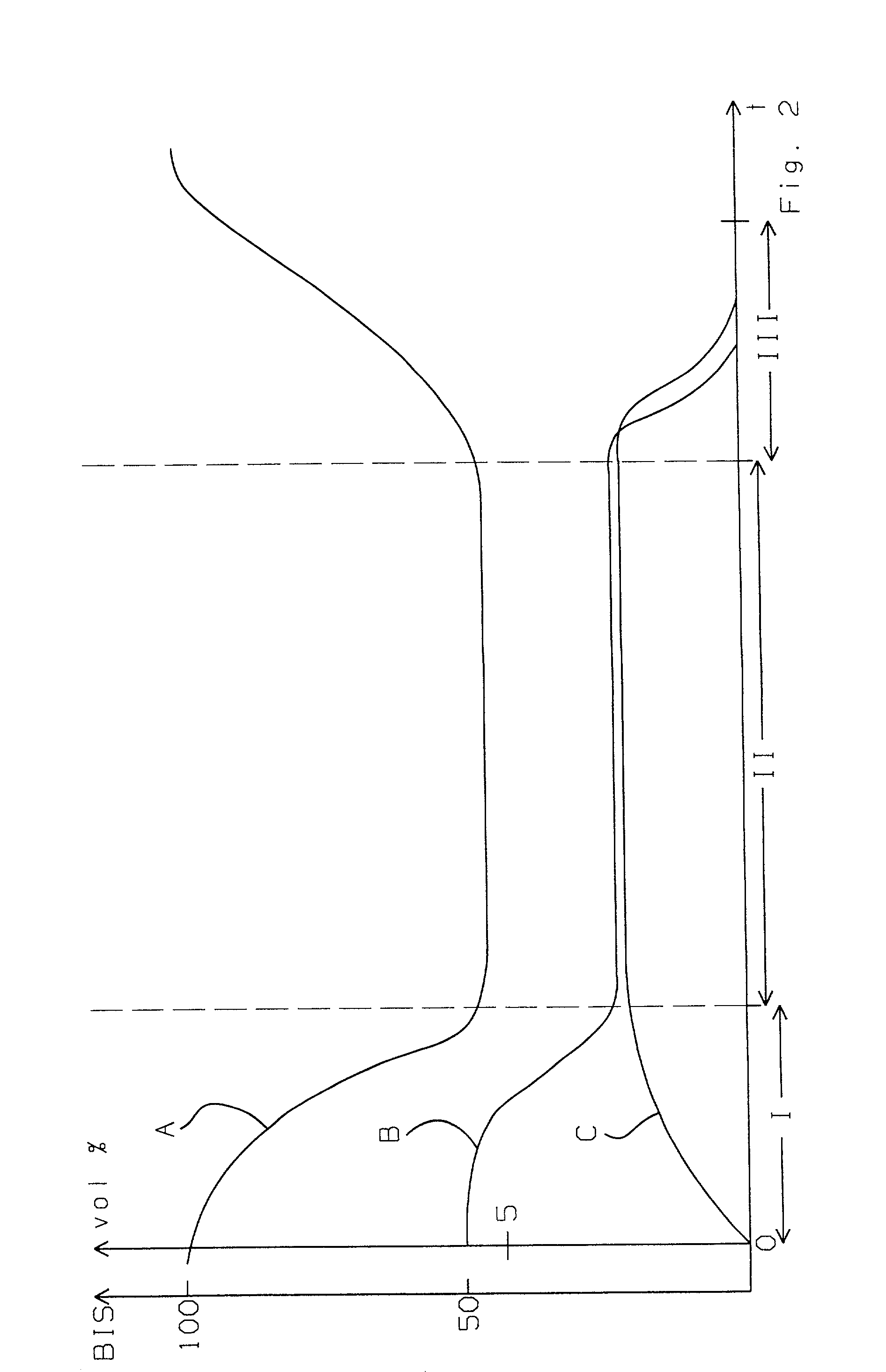
[0052] The set point of 50 is reached by BIS A. There are corresponding value pairs for BIS A and the expiratory sevoflurane concentration C. Even though no disturbances can be recognized, one of the two values moves out of the permissible tolerance range. This is 45 to 55 for BIS A and, e.g., 1.8 vol. % to 2.6 vol. % for the expiratory sevoflurane concentration. An alarm is triggered by the control unit 22.
Login to View More PUM
 Abstract
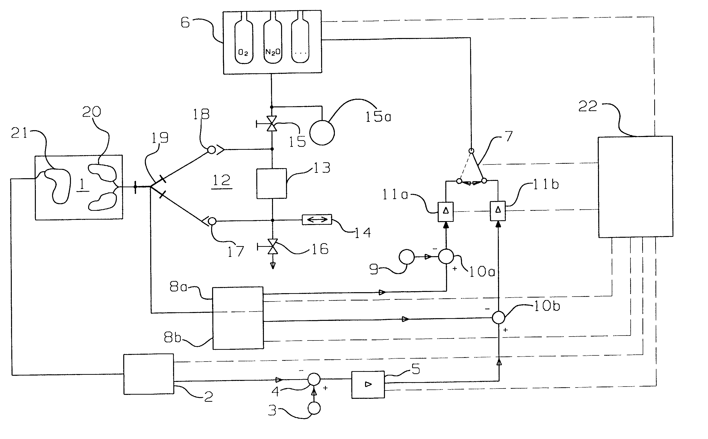
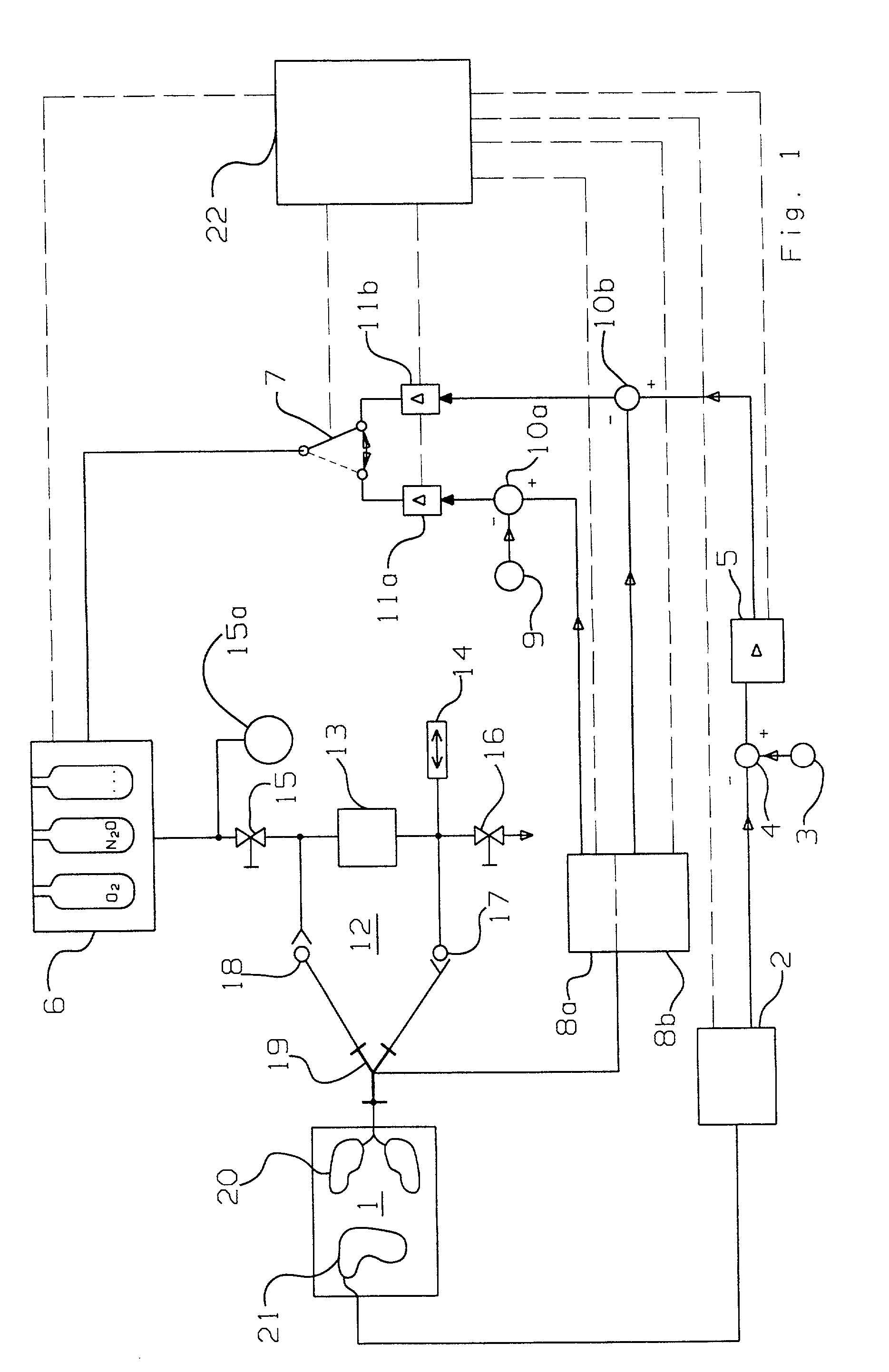
An arrangement with a control circuit for controlling a numerical value for patient respiration as well as to a process for controlling the numerical value. The numerical value is controlled on the basis of an evaluation of the EEG (electroencephalogram) of the patient (1) by an EEG sensor (2), e.g., by determining the so-called BIS (bispectral index). A control of the inspiratory gaseous anesthetic concentrations is cascaded to the control of the EEG value in the manner of a cascade circuit. This has the advantage that a metering device (6) belonging to the arrangement meters a gaseous anesthetic mixture directly according to the patient's needs. As an alternative, the control of the numerical value is performed on the basis of an evaluation of the expiratory gaseous anesthetic concentrations resolved for individual breaths at the Y-piece (19) of the respiration circuit (12) by a gaseous anesthetic sensor (8a), preferably an infrared optical gas sensor.
Description
[0001] The present invention pertains to an arrangement with a control circuit for controlling a numerical value for patient respiration as well as to the control of the numerical value.[0002] The control of the flow of a flowing medium, especially a gas, by means of valves via a cascade control circuit is described in EP 483 401 B1. It can be used for the respiration of humans and animals for the valve-controlled supply and removal of a gaseous anesthetic. The control parameter of the first control circuit is the flow, and the position of the valves or the current and the voltage for actuating the valves may be the control parameters of the second control circuit.[0003] A device and a process for the automation of peripheral anesthesia, which are based on measured values determined on the patient, have been known from EP 236 513 A1. The metering of anesthetics is preferably controlled there on the basis of an electromyelogram by means of electrodes distributed locally on the patien...
Claims
Login to View More Application Information
Patent Timeline
 Patent Type & AuthorityApplications(United States)
IPC IPC(8): A61B5/0476A61M16/01A61M16/10A61M16/22
CPCA61B5/0476A61M16/01A61M16/10A61M16/22A61M2016/1035A61M2230/10A61M2230/437A61M16/085A61B5/369A61B5/372
InventorDITTMANN, RALFGRUNITZ-POST, SWENLEONHARDT, STEFFENGENTILINI, ANDREAGLATTFELDER, ADOLPHMORARI, MANFREDSCHNIDER, THOMASZBINDEN, ALEXANDER M.
OwnerDRAGERWERK AG