
Method and systems for control of acceleration pulses generated by HYGE type crash simulation sleds

Inactive Publication Date: 2002-03-07
TEST MEASUREMENT SYSTEMS INC
View PDF1 Cites 15 Cited by
  • Summary
  • Abstract
  • Description
  • Claims
  • Application Information

AI Technical Summary

Problems solved by technology

The metering pin controlled force output works well, but is cumbersome and time-consuming to change to another force-time profile, requiring disassembly of the Set and Load Cylinders and removal and insertion of a different-shaped metering pin.

Method used


Image

  • Method and systems for control of acceleration pulses generated by HYGE type crash simulation sleds
  • Method and systems for control of acceleration pulses generated by HYGE type crash simulation sleds
  • Method and systems for control of acceleration pulses generated by HYGE type crash simulation sleds

Examples


Embodiment Construction

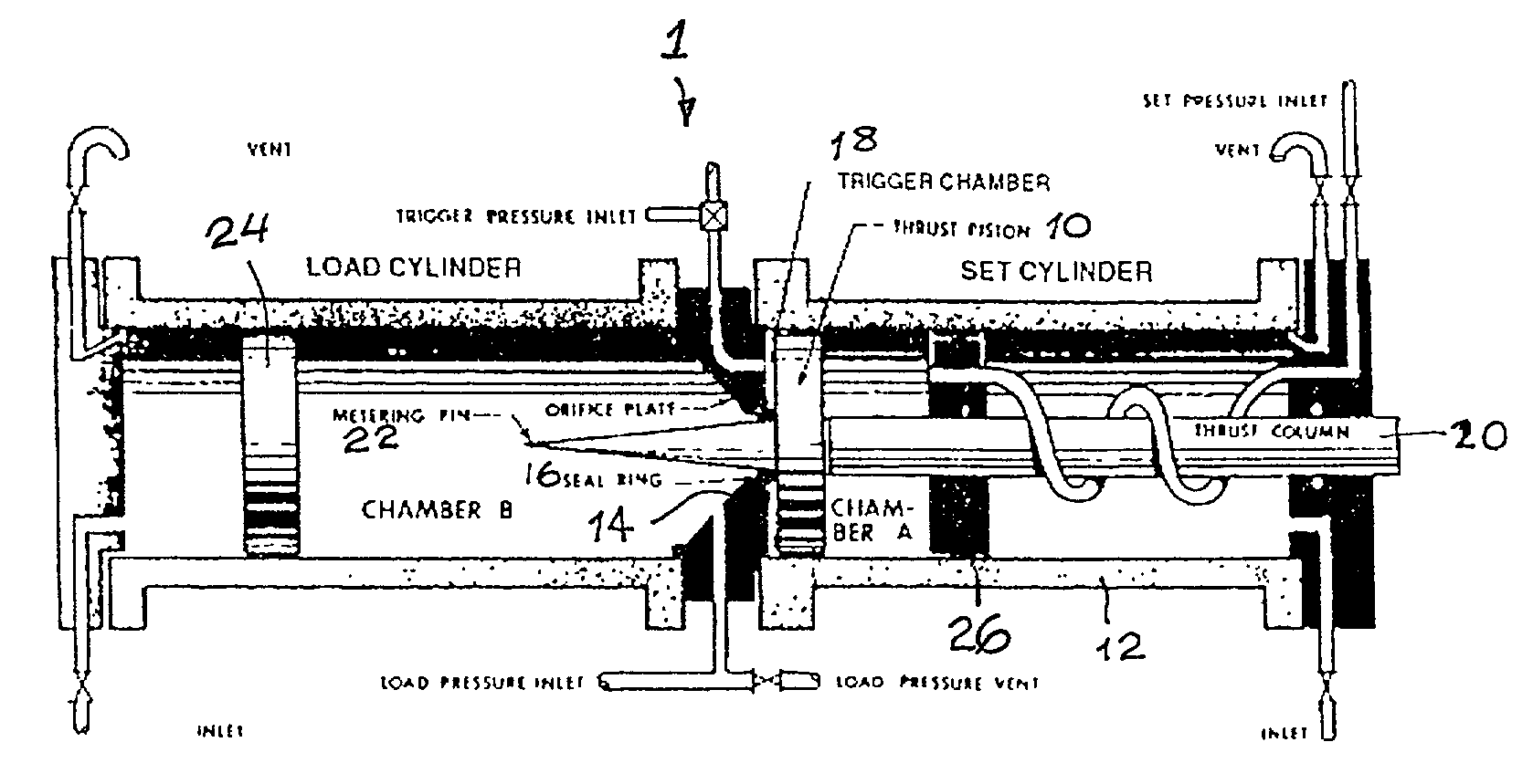
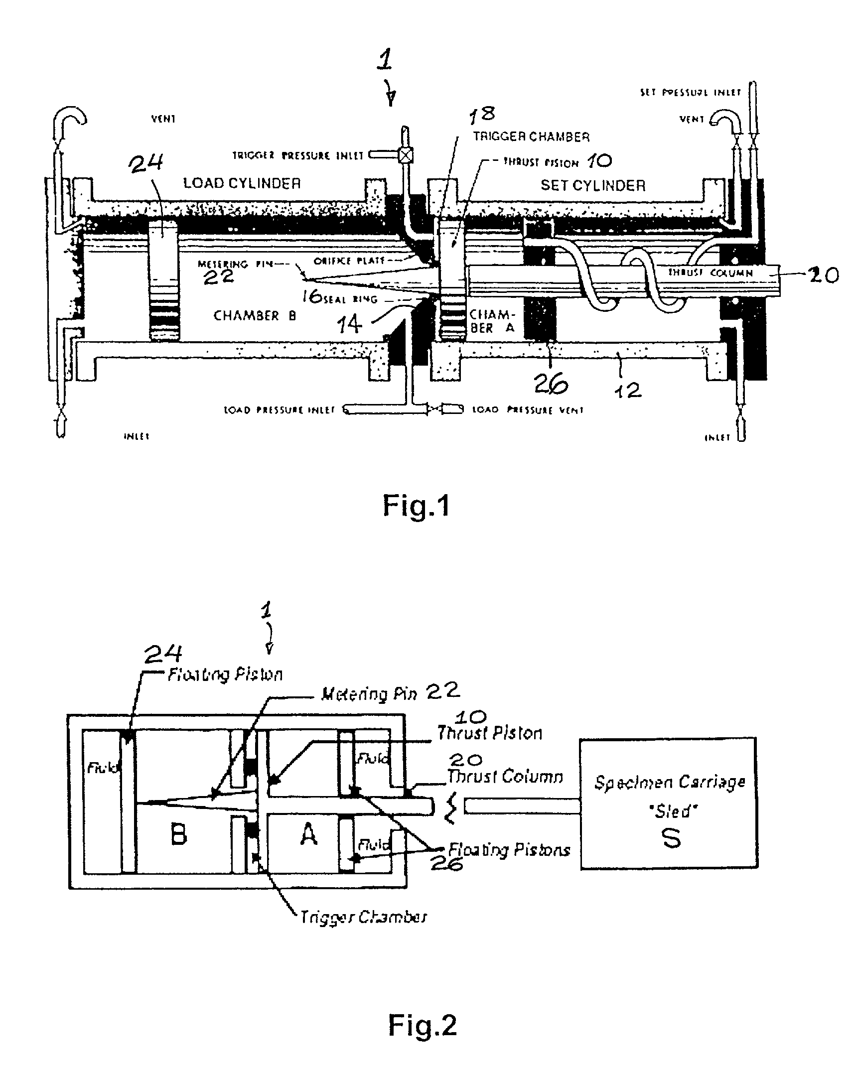
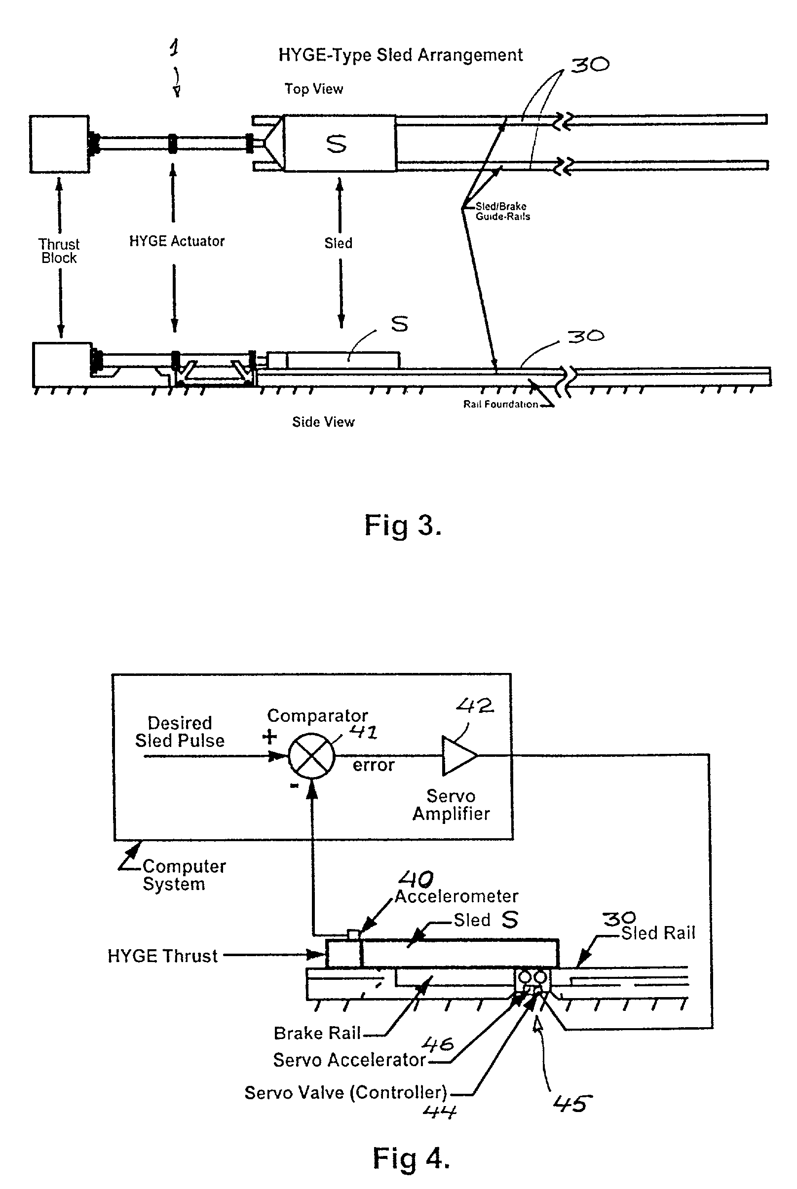
[0014] The accelerator may be composed of servo-controlled brakes (indicated generally at 45 in FIG. 4) to rapidly vary the total force applied to the sled, or an active actuator to rapidly apply either additional accelerating or retarding force to the sled in a dynamically varying and controlled manner, which variation shall depend upon the acceleration being sensed by a sled-mounted accelerometer then being subtracted from the desired acceleration value with the difference (error value) being used to control the application of sled acceleration that is appropriate to decrease the acceleration error. Such an accelerator may be applied to the thrust column as it extends from the actuator during firing, to a specially contoured metering pin inside of Chamber B, to the sled via a its braking system, to the sled via a set of auxiliary brakes or active actuator(s), or to the sled via disk brake controlled cable-reel winch(es) attached to the HYGE actuator case (or foundation) with the w...


PUM


Abstract

An acceleration pulse modulation method for HYGE-type crash simulation sleds uses servo-controlled accelerators on moveable parts of the crash simulator components and acceleration measurement instrumentation for comparison of measure acceleration of the sled with a desired acceleration to enable dynamic adjustment of the total accelerating force applied to the sled via servo-controlled accelerators, based upon measured acceleration error in order to eliminate acceleration error.

Description

[0001] The present invention pertains generally to the control of the acceleration pulse delivered by HYGE-Type crash simulation sleds used in safety testing of vehicle components.BACKGROUD OF THE INVENTION[0002] The HYGE system derives its powerful thrust force from an actuator assembly 1 which uses differential gas pressure acting on the two faces of a thrust piston 10 in a closed cylinder 12, as shown in FIG. 1. The cylinder is separated into two chambers A, B by an orifice plate 14. A relatively low gas pressure in chamber A, known as the Set Cylinder, forces the thrust piston 10 against a seal ring 16 on the orifice plate 17. The area of the entire thrust piston face is exposed to the gas pressure in chamber A, defined by floating pistons 26 opposed to thrust piston 10. On the other side of the piston, only the small area within the seal is exposed, through the orifice opening, to the gas pressure in chamber B, known as the Load Cylinder, in which a floating piston 24 is locate...

Claims


Application Information

Patent Timeline
IPC IPC(8): G01N3/00G01N3/30
CPCG01N3/307G01N2203/001G01N2203/0044
Inventor POTTS, GERALD R.
Owner TEST MEASUREMENT SYSTEMS INC
Learn More