This helps you quickly interpret patents by identifying the three key elements:
Problems solved by technology
Method used
Benefits of technology
Benefits of technology
[0047] As explained above, in the electronic tag device according to the present invention, because an electronic tag is freely moveable inside the outer tube, by tilting a single outer tube as is, or a group of outer tubes lined up together, the electronic tag can move freely therein and will be even with the end thereof. Because of this, the power emissions in a reading device for reading data recorded on an electronic tag are not exceptionally large. Even if an electronic tag is in a tilted position, it can be read accurately and reliably.[0048] Thus, when rolls of fabric are lined up, even if the direction and position of the attached electronic tags with respect to the antenna is uneven, they can be effectively and appropriately used.[0049] FIG. 1[0050] Figure showing the first embodiment of the electronic tag device of the invention.[0051] FIG. 2[0052] Figure showing the inner tube used in the first embodiment.[0053] FIG. 3[0054] Figure showing the third embodiment of the electronic tag device of the invention.[0055] FIG. 4[0056] Figure showing the inner tube used in the third embodiment.[0057] FIG. 5[0058] Figure showing the fourth embodiment of the electronic tag device of the invention.[0059] FIG. 6[0060] Figure showing the fifth embodiment of the electronic tag device of the invention.[0061] FIG. 7[0062] Figure showing the sixth embodiment of the electronic tag device of the invention.[0063] FIG. 8[0064] Figure showing the seventh embodiment of the electronic tag device of the invention.[0065] FIG. 9[0066] Figure showing the eighth embodiment of the electronic tag device of the invention.[0067] FIG. 10[0068] Figure illustrating the quick reading of a plurality of the electronic tags applying the embodiments of the invention.[0069] FIG. 11[0070] Figure illustrating a conventional electronic tag in use attached to a fabric core.[0071] FIG. 12[0072] Figure illustrating electronic tags applied to a conventional selection of a plurality of textiles of differing types.[0073] FIG. 13[0074] Figure illustrating the usage of a fabric on a conventional cylindrical core and an electronic tag attached thereto.[0075] FIG. 14[0076] Figure illustrating the quick reading of an entire stack of a plurality of the core and fabric seen in FIG. 13.[0077] FIG. 15[0078] Figure showing the relationship between the coil on the antenna-side in the reader and the coil in the electronic tag.
Problems solved by technology
When this type of tag is made out of paper, it is necessary to perform the work of producing it and printing the price and the like thereon, and it is difficult to read.
Method used
Image
Click on the blue label to locate the original text in one second.
Reading with bidirectional positioning of images and text.
Examples
first embodiment
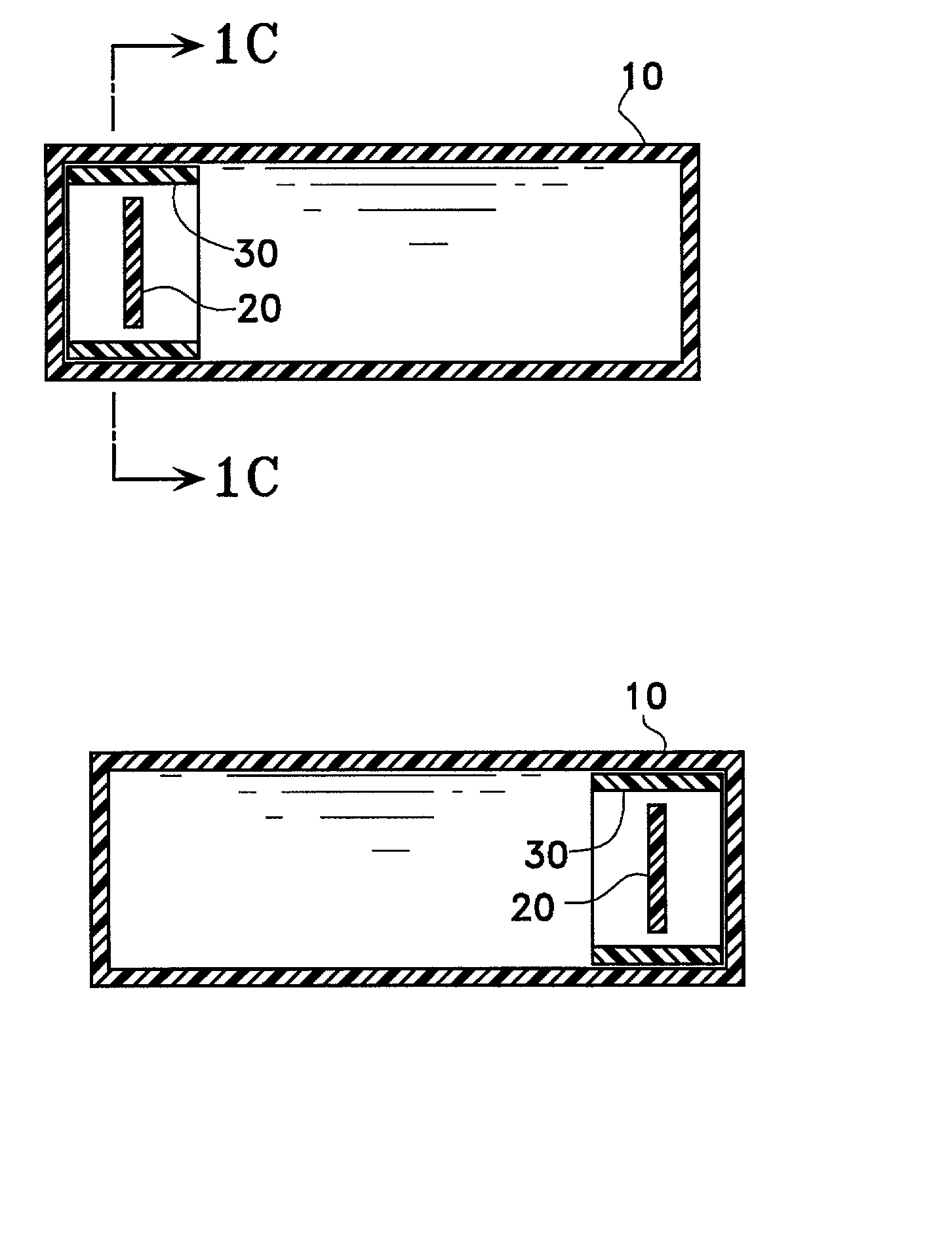
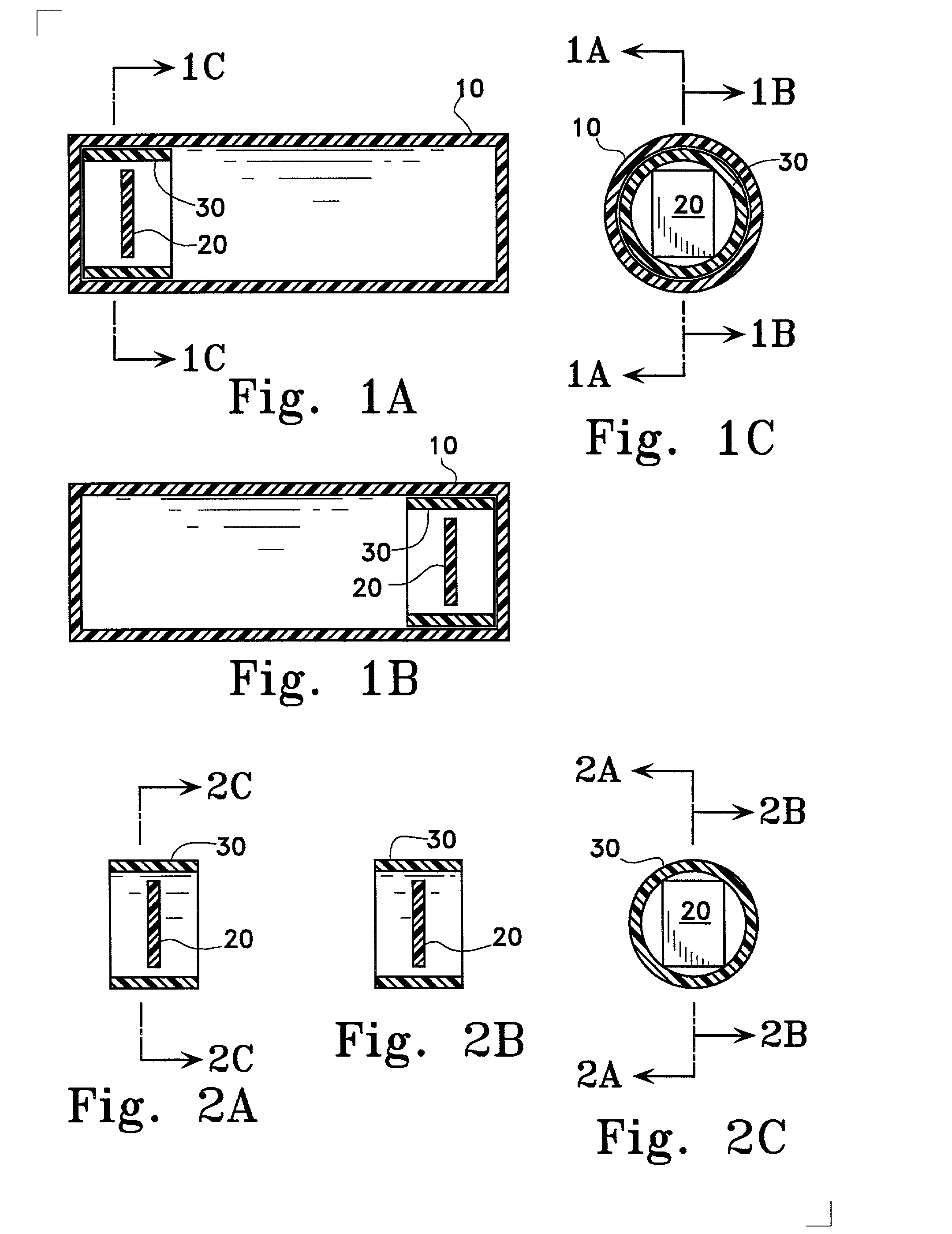
[0024] In FIG. 1, (A) is vertical cross-section view, (B) is a horizontal cross-sectional view (from above), and (C) is a side cross-sectional view (from the front). In the figures showing the following embodiments, when the same three views are shown, each cross-section will be shown in the same order.
[0025] In FIG. 1, 10 is an outer tube, 20 is an electronic tag, and 30 is an inner tube. A reading device, not shown in FIG. 1, is positioned below electronic tag 20. Inner tube 30 is moveable in the lengthwise direction (left to right in FIG. 1) of outer tube 10. Here, inner tube 30, outer tube 20, electronic tag 20, and the reading device make up the electronic tag device.
[0026] The outer circumference [sic] of a cross-section of inner tube 30 taken orthogonally with respect to the direction that inner tube 30 moves inside outer tube 10 (left to right in FIG. 1) is generally equal to the inner circumference of a cross-section of the outer tube 10. In this embodiment, both outer tube...
second embodiment
[0032] As a second embodiment of the present invention, it is acceptable for both the outer tube and the inner tube to have an angular shape. Here, the dimensions of the outer circumference and the inner circumference are as provided in the first embodiment. According to this configuration, the operational results of the electronic tag device are the same as those in the first embodiment.
third embodiment
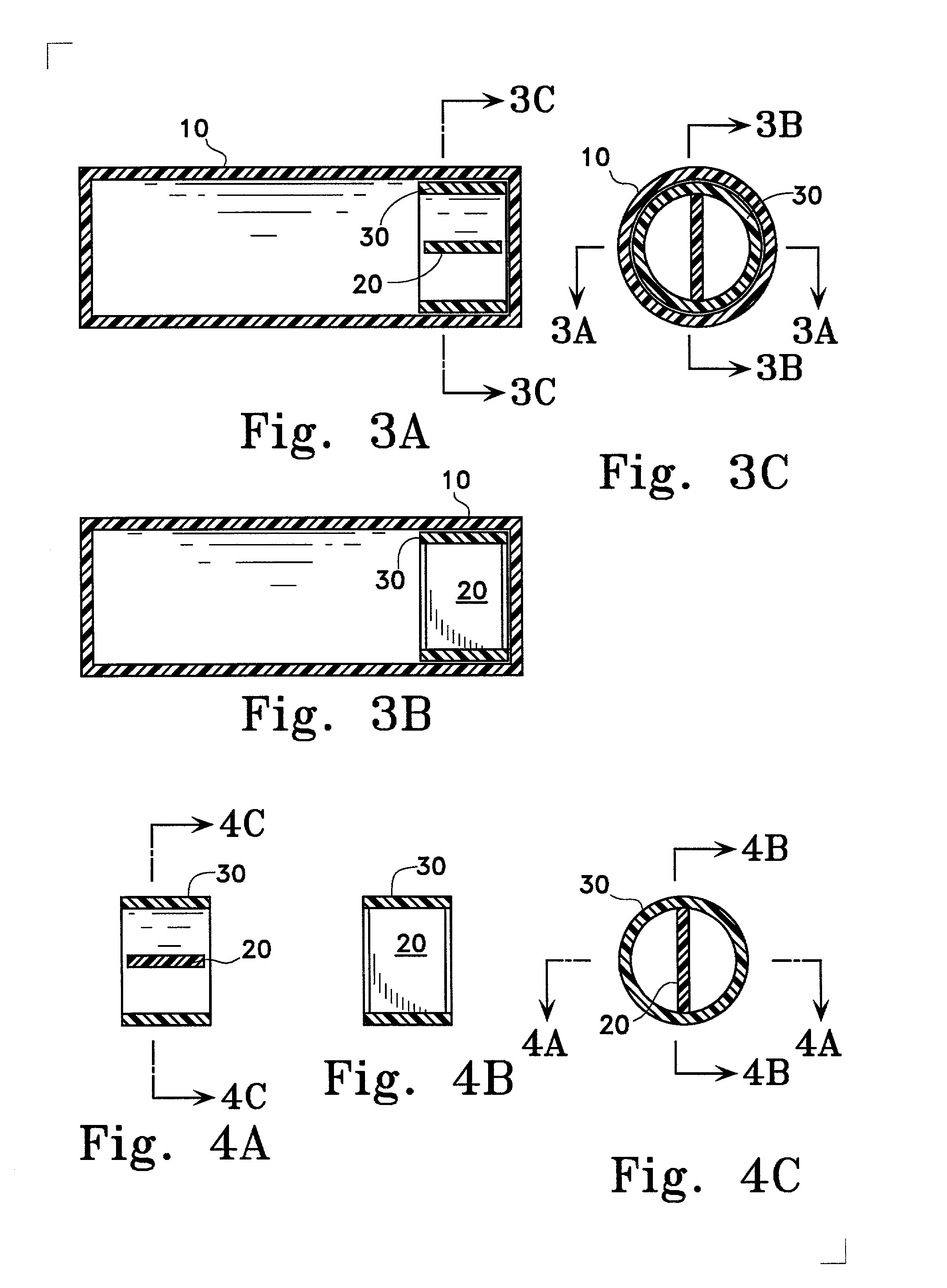
[0033] Next, a third embodiment of the present invention is shown in FIGS. 3 and 4. As shown in FIGS. 3 and 4, the outer tube 10, the electronic tag 20, and the inner tube 30 are the same as shown in the first embodiment. The electronic tag 20 is in inner tube 30, but a point of difference is that electronic tag 20 is held in inner tube 30 such that it is parallel with respect to the direction of the movement of inner tube 30.
[0034] When electronic tag 20 is disposed in this manner, the movement of inner tube 30 is the same as in FIGS. 1 and 2. However, when a reading device is put in the same place as in FIG. 1, the relationship between it and electronic tag 20 is worse than that shown in FIG. 1, and thus it is better to place it the upper direction with respect to the plane of the paper of FIG. 3 (A).
PUM
Abstract
To offer a configuration such that the entire status of a large volume of products to which an electronic tag is attached can easily and accurately be distinguished via an antenna. Means for Achieving Objective: The invention comprises an inner tube 30 installed with an electronic tag 20, an outer tube 10 within which the inner tube 30 is moveable lengthwise, and a reader for data recorded in the electronic tag 20; and the cross-sectional shape of the inner tube 30 in a plane perpendicular to the direction in which it moves within the outer tube 30 is formed so as to be almost equivalent to the cross-sectional shape of the outer tube 10 in a similar plane. A weight may be equipped within the inner tube 30. Alternatively, it may be filled with a liquid of a slightly high specific gravity so that the electronic tag 20 floats. When a plurality of outer tubes 10 are aligned, the electronic tags 20 can all be aligned in similar positions.
Description
[0001] 1. Field of Industrial Use[0002] The present invention relates to a suitable electronic tag device attached and used on a core around which is wrapped a flexible material such as a textile, cloth, or the like.[0003] 2. Prior Art[0004] In the prior art, when information regarding the material, price and the like of an item is to be printed on items sold at retail, it is printed on a piece of paper known as a tag and attached to the item in order to greatly reduce costs. When this type of tag is made out of paper, it is necessary to perform the work of producing it and printing the price and the like thereon, and it is difficult to read. Thus, in recent years paper tags are being converted to electronic tags that can be electronically processed, as shown in FIG. 11. Because information is recorded thereon by means of an electronic device, the information is easy to read and does not easily disappear. This has a big effect on the ability of store employees to confirm sales by me...
Claims
Application Information
Patent Timeline
Application Date:The date an application was filed.
Publication Date:The date a patent or application was officially published.
First Publication Date:The earliest publication date of a patent with the same application number.
Issue Date:Publication date of the patent grant document.
PCT Entry Date:The Entry date of PCT National Phase.
Estimated Expiry Date:The statutory expiry date of a patent right according to the Patent Law, and it is the longest term of protection that the patent right can achieve without the termination of the patent right due to other reasons(Term extension factor has been taken into account ).
Invalid Date:Actual expiry date is based on effective date or publication date of legal transaction data of invalid patent.

