
Forward bearing arrangement for the tilting cab of a truck

a technology for forward bearings and trucks, which is applied in the direction of bearings, loading-carrying vehicle superstructures, spring/damper design characteristics, etc., can solve the problems of cardanic loads, insufficient long-lived pure plain bearings, and disadvantages

Inactive Publication Date: 2002-03-07
MANNESMANN BOGE
View PDF0 Cites 10 Cited by
  • Summary
  • Abstract
  • Description
  • Claims
  • Application Information

AI Technical Summary

Benefits of technology

[0008] To achieve this object, in accordance with the invention the bearing includes a rubber bearing with a plain bearing coaxial to it. It is advantageous here that the customers' requirements for comfort during operation of the vehicle, for a long service life (vehicle life), and simultaneously for favorable torsional properties when the cab is tilted are all accommodated when the forward bearing arrangement consists of this combination of a rubber bearing and a plain bearing.
[0010] In accordance with another essential feature of the invention, it is provided that the rubber bearing is mounted on the bearing axle and the plain bearing is mounted between the rubber bearing and the bearing shell radially on the outside. Because the two different functions are separated, both the rubber bearing and the plain bearing can be designed at low cost to meet the minimum appropriate requirements.
[0011] In accordance with another essential feature, an arresting device is provided to prevent the plain bearing from rotating. By means of an arresting device of this type, it is therefore possible to "deactivate" the plain bearing, as it were, while the vehicle is being driven.
[0012] It is also provided that the arresting device is under pretension and allows the plain bearing to rotate once a certain predetermined force is exceeded. As an arresting device, the plain bearing has at least one recess in the outside circumference, in which a spring-loaded element engages. It is advantageous for this element to be ball.

Problems solved by technology

A bearing arrangement of this type is based on the following problems: To achieve a sufficiently comfortable ride, the cab bearings must allow the longest possible distances, but these are predetermined by the design and by the material of the elastic bearings.
Relatively soft elastic bearings, which allow relatively large spring excursion, however, turn out to be disadvantageous when the cab is tilted.
In addition, there are also cardanic loads.
Pure plain bearings have not proven to be sufficiently long-lived at this installation point, because the continually alternating loads in a relatively small area of the bearing (point load), which area is always the same, leads to premature wear, even when the bearings are designed to be greased.
In addition, plain bearings are difficult and expensive to produce because of the very close manufacturing tolerances, and they do not have any damping properties at all.
Because plain bearings have no elasticity, furthermore, high edge pressures also occur under cardanic load.

Method used


Image

  • Forward bearing arrangement for the tilting cab of a truck
  • Forward bearing arrangement for the tilting cab of a truck
  • Forward bearing arrangement for the tilting cab of a truck

Examples


Embodiment Construction

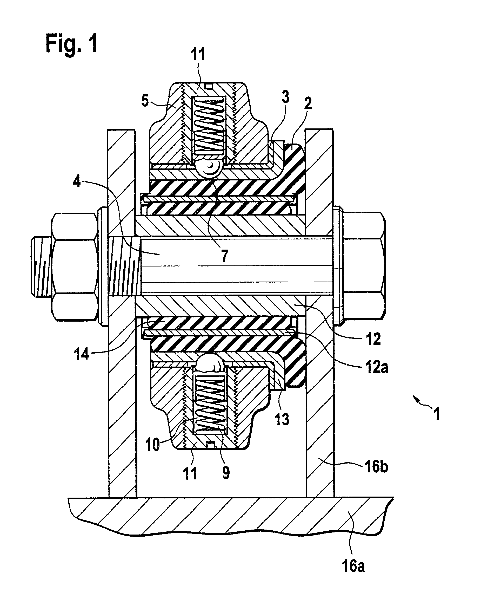
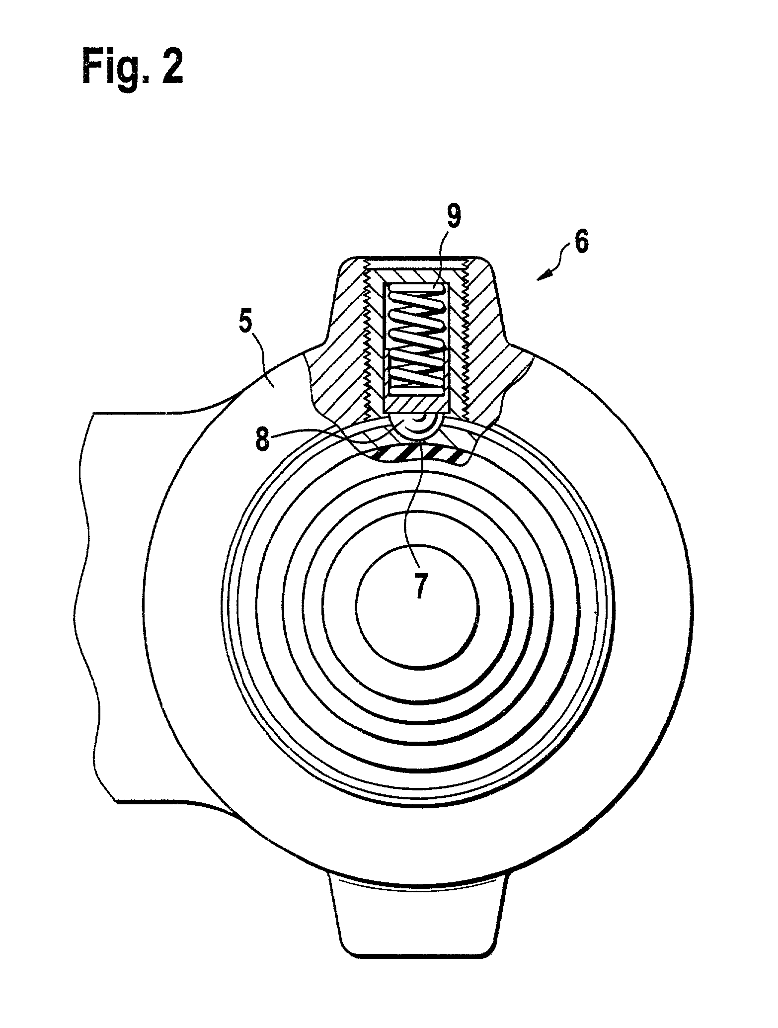
[0022] The forward bearing arrangement shown in FIGS. 1 and 2 for the tilting cab of a truck consists essentially of the bearing brackets 16a, 16b; the bearing axle 4, on which the bearing 1 is mounted; and the bearing shell 5, which is fixed to the floor of the cab in a manner not shown in the drawings.

[0023] The bearing 1 itself consists of a rubber bearing 2, a plain bearing 3, and an arresting device 6. The rubber bearing 2, which is radially on the inside, is mounted on the bearing axle 4; it has an inner bush 12, an outer bush 13, and a rubber part 14 between them. Radially outside the rubber bearing 2 is the plain bearing 3, in which there is a hole 7, by means of which a ball 8 can produce a positive connection with the outer bush 13 of the rubber bearing 2.

[0024] The arresting device 6 consists here of a screwed-in part 11 with a bore 10, in which not only the ball 8 but also a spring 9 are housed, so that, when the cab is tilted beyond a certain point, the ball 8 releases ...


PUM


Abstract

The cab is supported at the front by elastic bearings mounted on bearing axles in alignment with each other and supported by at least two brackets attached to the vehicle frame. The elastic bearings are mounted in bearing shells attached to the floor of the cab. Each elastic bearing includes a rubber bearing with a plain bearing coaxial to it. An arresting device between the plain bearing and the elastic bearing presents relative rotation until a threshold torsional load is exceeded.

Description

[0001] 1. Field of the Invention[0002] The invention pertains to a forward bearing arrangement for the tilting cab of a truck, with at least two brackets fastened to the vehicle frame, on which the cab is supported at the front by way of elastic bearings mounted on bearing axles which are aligned with each other, which bearings are mounted in bearing shells fastened to the floor of the cab.[0003] 2. Description of the Related Art[0004] Bearing arrangements for tilting cabs of trucks are already known (e.g., DE 195 37 722 A1, EP 0 635 419 B1). A bearing arrangement of this type is based on the following problems: To achieve a sufficiently comfortable ride, the cab bearings must allow the longest possible distances, but these are predetermined by the design and by the material of the elastic bearings. Relatively soft elastic bearings, which allow relatively large spring excursion, however, turn out to be disadvantageous when the cab is tilted.[0005] In the bearings of the tilting cab ...

Claims


Application Information

Patent Timeline
Patent Type & Authority Applications(United States)
IPC IPC(8): B62D33/067
CPCB62D33/067F16F1/3842F16F2230/0076
Inventor TESTROET, MARTINSTEINHOFER, RALF
Owner MANNESMANN BOGE
Learn More