Elevator, particularly a traction sheave elevator

a technology of elevators and sheave elevators, which is applied in the field of elevators, can solve the problems of reducing building space, increasing the overall cost of elevators or elevators, and the total cross sectional area of elevator shafts cannot be used for elevator cages, so as to reduce construction costs and the effect of total cost of elevators

Inactive Publication Date: 2002-03-14
THYSSENKRUPP AUFZUGSWERKE GMBH
View PDF0 Cites 4 Cited by
  • Summary
  • Abstract
  • Description
  • Claims
  • Application Information

AI Technical Summary

Benefits of technology

0007] The objective of the present invention is therefore to provide an elevator with an elevator drive of usual size arranged in the elevator shaft, without increasing the shaft head h...

Problems solved by technology

The disadvantage here is that because of the arrangement of the drive in the elevator shaft the total cross sectional area of the elevator shaft cannot be used for the elevator cage.
The larger size of the elevator shaft necessary for a specific elevator cage results in higher overall costs for the elevator or a reduction in building space.
A further disadvantage is that the drive with a large elevator cage cannot exceed a specific size, without the need for recesses for example in the shaft wall.
S...

Method used


Image

  • Elevator, particularly a traction sheave elevator
  • Elevator, particularly a traction sheave elevator
  • Elevator, particularly a traction sheave elevator

Examples


Embodiment Construction

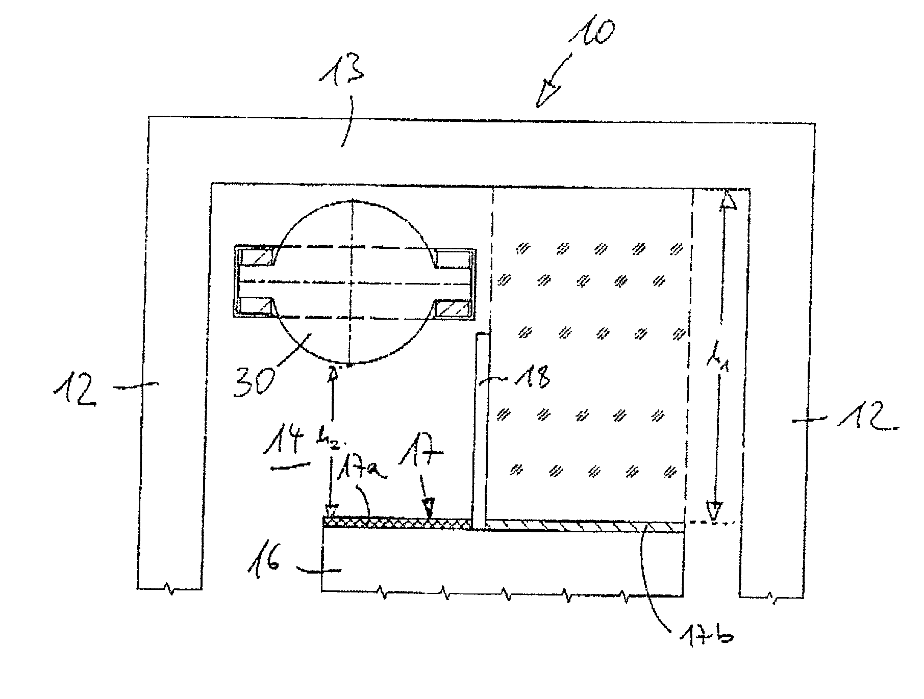
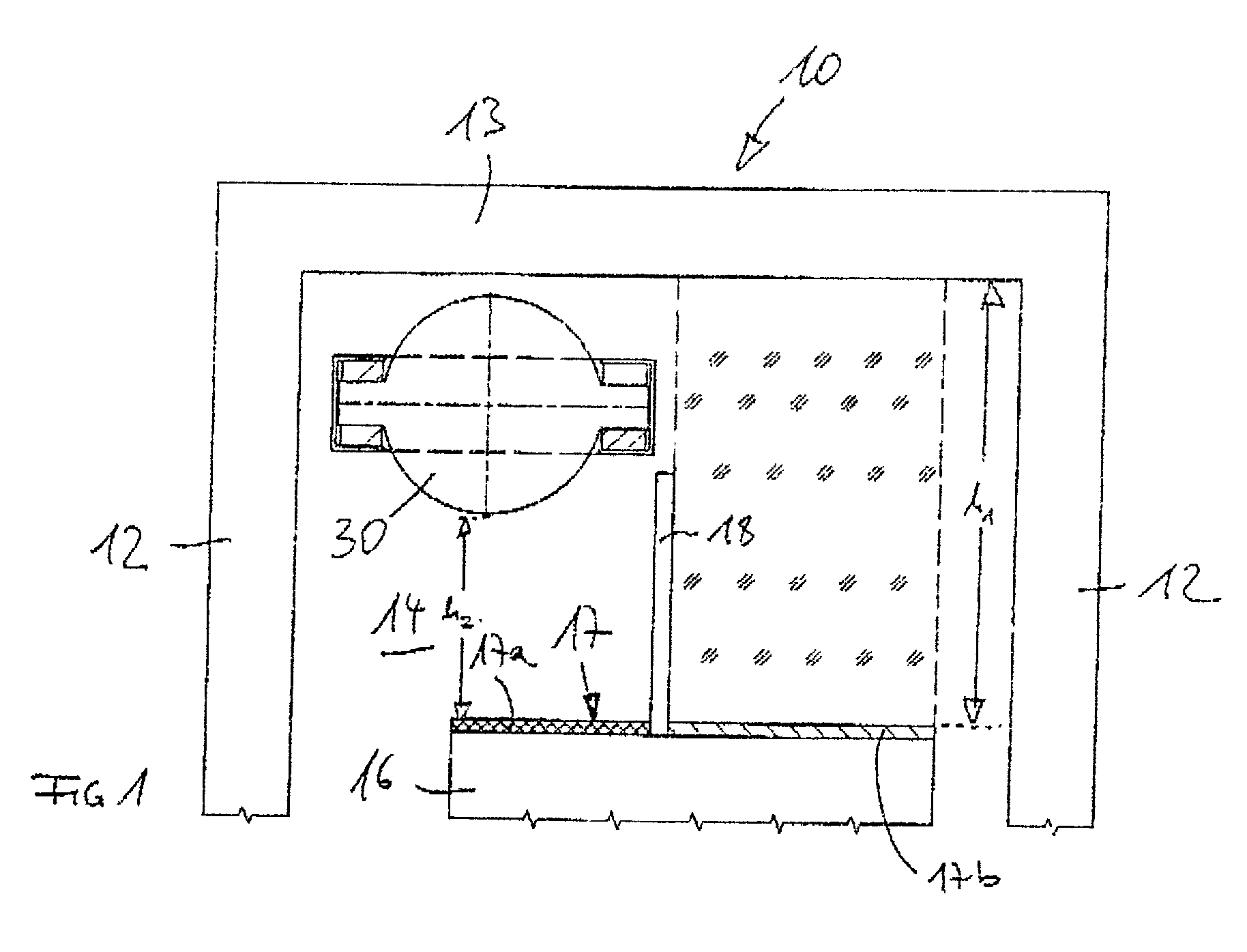
[0032] FIG. 1 shows in a schematic view a cross section of the top section of an elevator 10 according to the invention. The elevator 10 comprises an elevator cage 16 arranged in an elevator shaft 14 with an elevator cage roof 17. In the drawing of FIG. 1 the elevator cage 16 is in its upper stop position and only its roof section is shown.

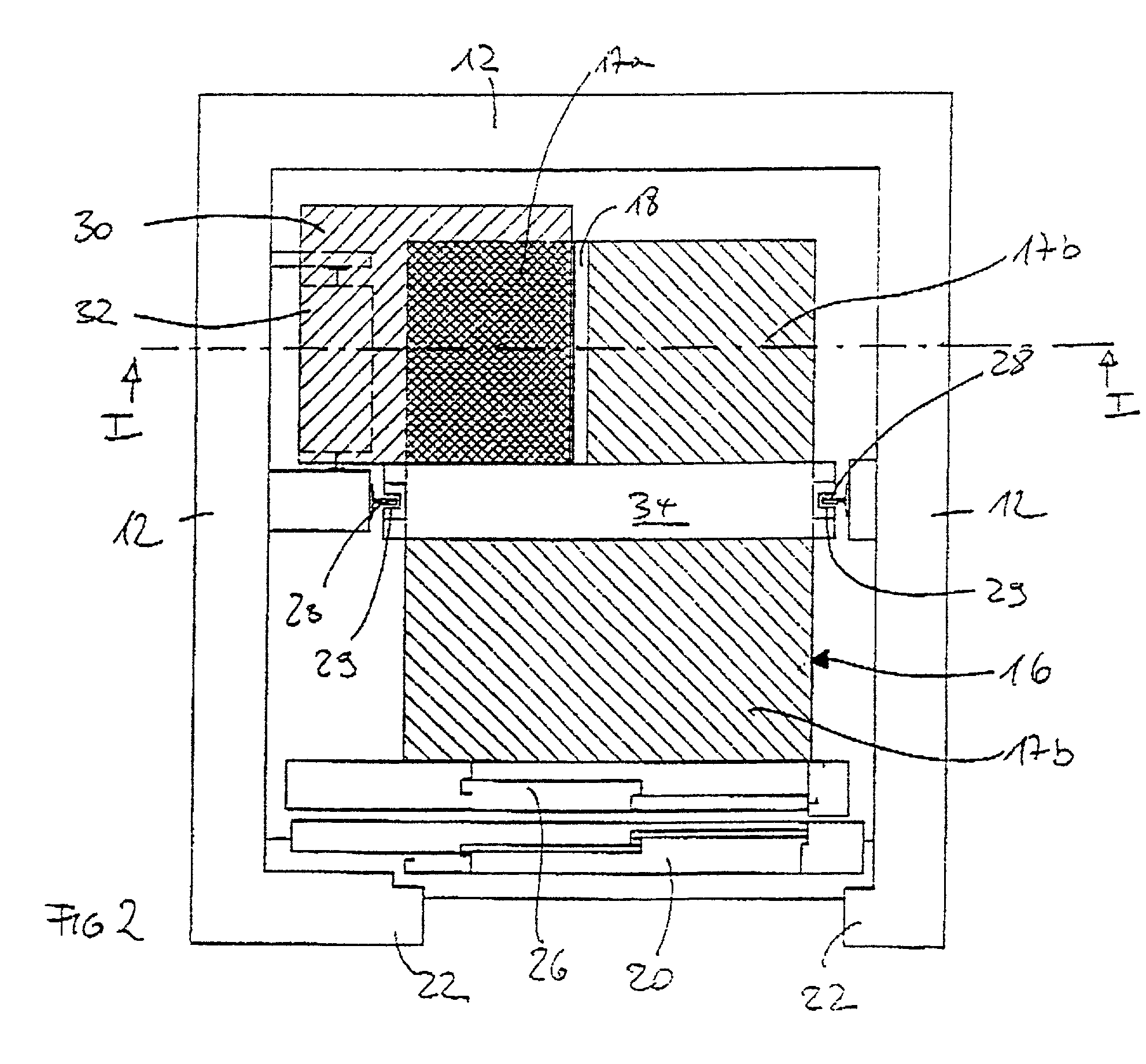
[0033] The elevator shaft 14 of the elevator 10 is delimited by shaft walls 12 and a shaft ceiling 13. On the elevator landing in the shaft wall 12 a door opening delimited by a reveal 22 is provided, which is closed by means of a shaft door 20 (cf. FIG. 2). An elevator cage door 26 is assigned to the elevator cage 16 which to open the passage between the elevator cage 16 and the elevator landing can be opened together with the shaft door 20.

[0034] In the elevator shaft 14 a drive for the elevator cage 16 is arranged for its vertical movement in the elevator shaft 14. The drive comprises a drive machine 30 which is arranged in the shaft head above...


PUM


Abstract

An elevator with an elevator cage guided in a shaft between a shaft head and a shaft pit, having an elevator cage roof and an elevator cage base and a drive, which is connected by at least one hauling cable with the elevator cage, whereby in particular for performing maintenance work the elevator cage roof is designed to be accessible, whereby the drive is arranged at least partly in the shaft head over a first region of the elevator cage roof and the accessibility of the elevator cage roof is restricted to a second region.

Description

THE FIELD OF THE INVENTION[0001] The present invention relates to an elevator, in particular a traction sheave elevator.[0002] Usually elevators with traction sheave drive have an elevator cage arranged in an elevator shaft and on the top a driving mechanism area, in which the control, driving mechanism and other elevator components are arranged. Here the cables of one traction sheave side run down to the elevator cage and of the other side to the counterbalance. So that maintenance staff can also stand on the elevator cage roof even during elevator operation to perform maintenance or installation work, for this propose a minimum safety area above the elevator cage roof is necessary which extends from the elevator cage roof in the upper elevator cage position to the lower edge of the components arranged above or up to the shaft ceiling. In general with such elevators with a driving mechanism area outside the shaft in the shaft head at least roller supports for the return pulleys of ...

Claims


Application Information

Patent Timeline
IPC IPC(8): B66B11/00B66B9/00
CPCB66B11/0045
Inventor REUTER, GUNTERFRHR. V. SCHOLLEY, HANS FERDINANDUNTERGASSER, HANSSCHULZ, JURGENBLICKLE, GUNTHERWEINMANN, HARTMUT
Owner THYSSENKRUPP AUFZUGSWERKE GMBH
Why Eureka
Try Eureka