Cutting insert for heavy turning operations

a cutting insert and heavy-duty technology, applied in the direction of cutting inserts, shaping cutters, manufacturing tools, etc., can solve the problems of requiring extensive and expensive grinding, mediocre lateral stability of cutting inserts, and weak dimensioning reasons

Inactive Publication Date: 2002-03-14
SANDVIK INTELLECTUAL PROPERTY AB
View PDF0 Cites 7 Cited by
  • Summary
  • Abstract
  • Description
  • Claims
  • Application Information

AI Technical Summary

Problems solved by technology

However, a disadvantage of this known cutting insert for heavy turning is that in practice it is suitable for grooving operations, but not for longitudinal turning, inasmuch as the lateral stability of the cutting insert is mediocre.
Thus, disturbances of the cutting insert longitudinally are only counteracted by the above-mentioned pin, which for technical, dimensioning reasons is comparatively weak.
Another disadvantage of the cutting insert is that it requires extensive and expensive grinding.
An additio

Method used


Image

  • Cutting insert for heavy turning operations
  • Cutting insert for heavy turning operations
  • Cutting insert for heavy turning operations

Examples


Embodiment Construction

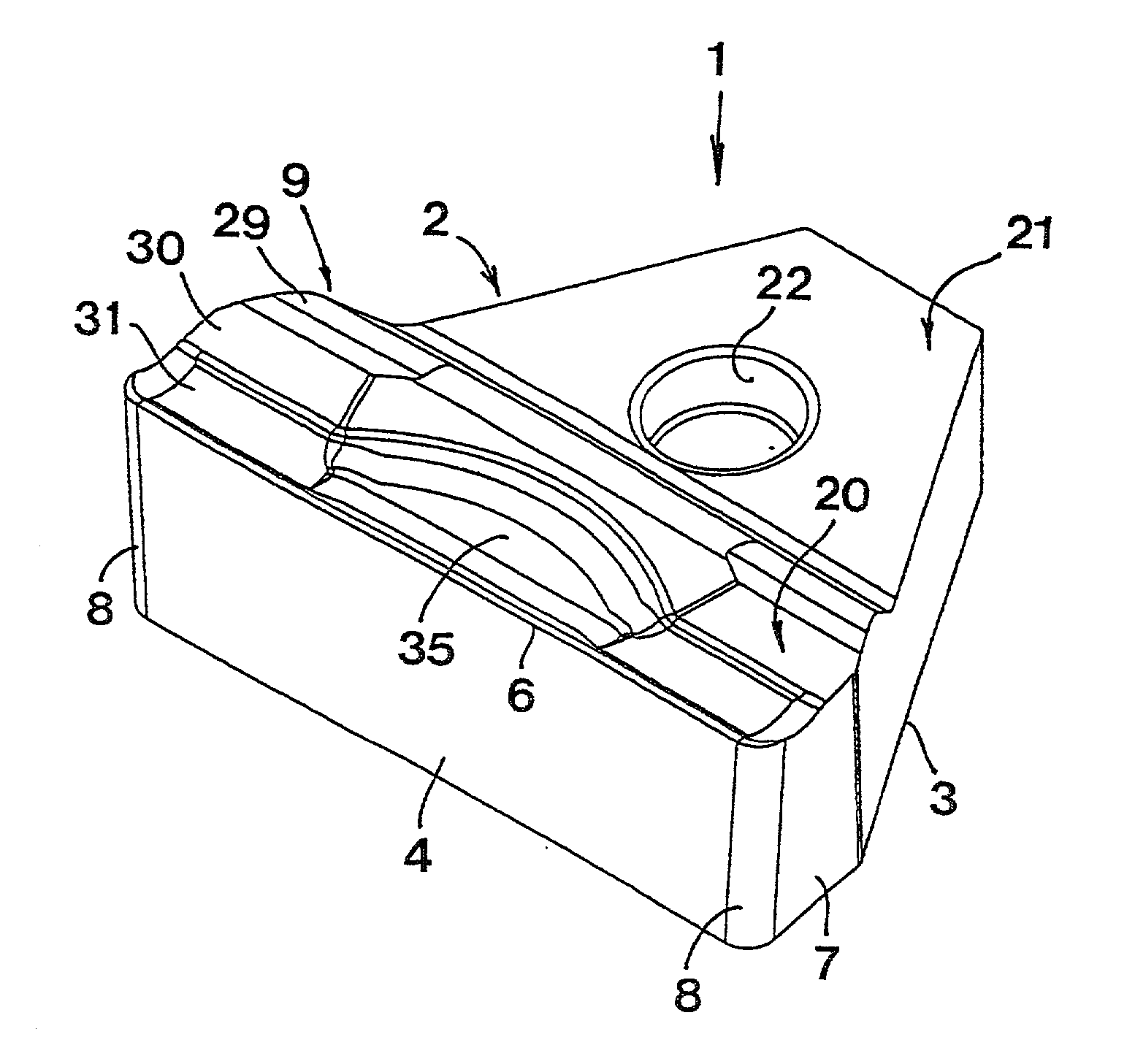
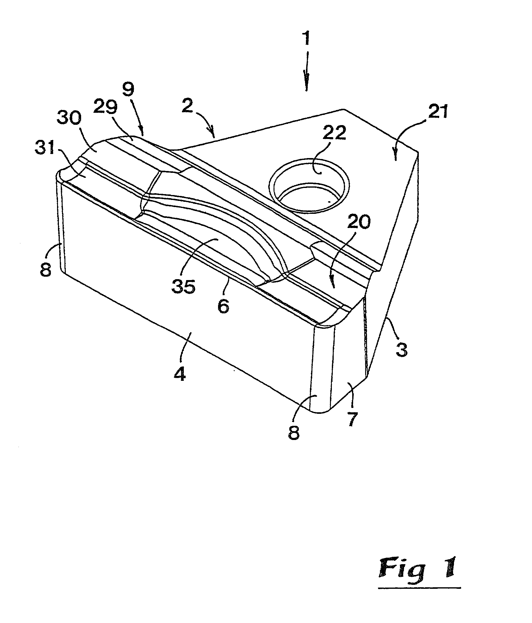
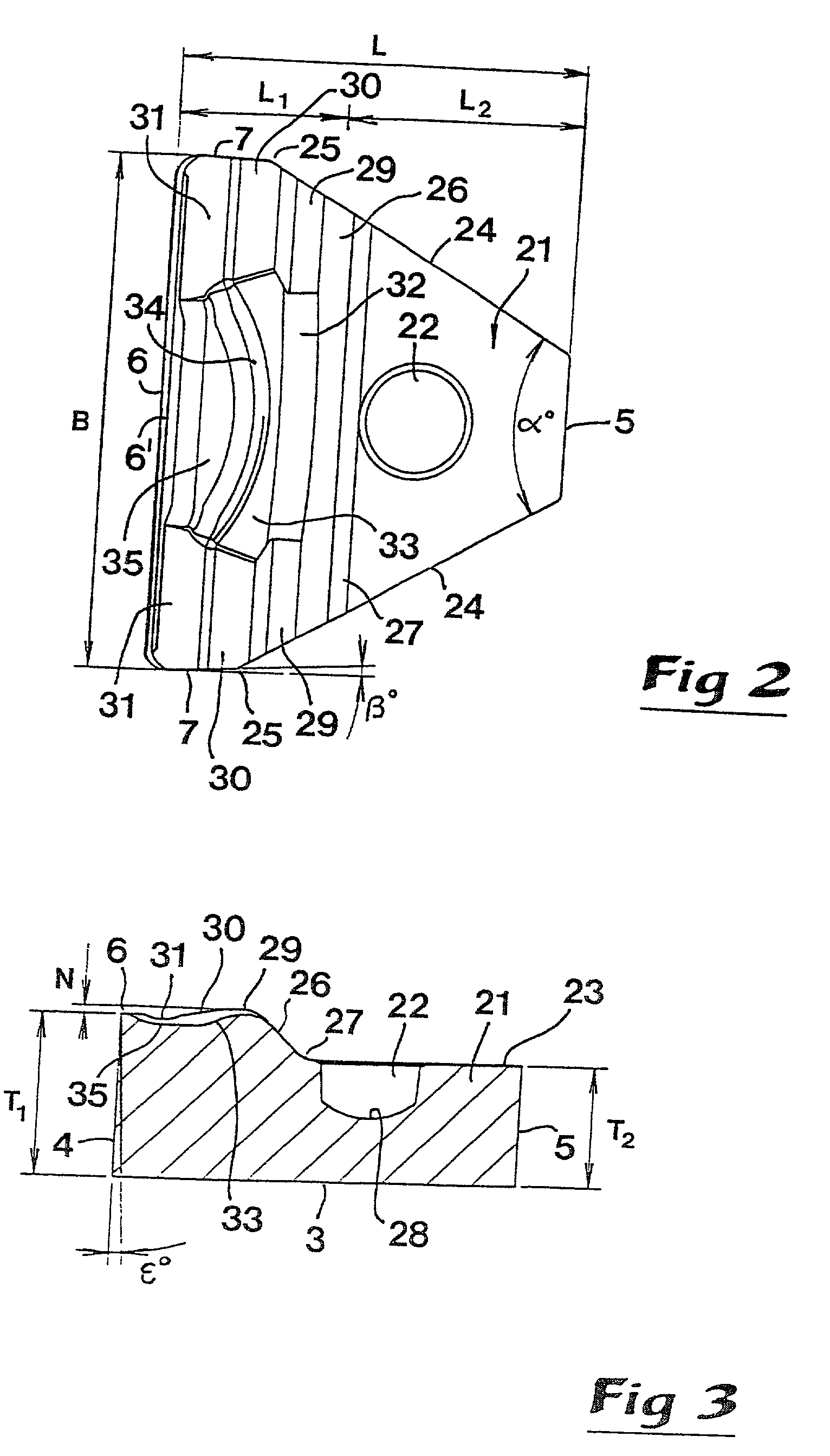
[0017] In FIGS. 1-3, a first embodiment of a cutting insert 1 according to the invention is illustrated. The cutting insert is defined by a top side 2 and an opposite bottom side 3. Between the top side 2 and the bottom side 3, a front surface 4 extends which is situated opposite a rear end surface 5. In the area between the front surface and the top side 2, a cutting edge 6 is formed, which in a conventional way consists of a sharp edge between the front surface 4 and a plane reinforcement surface or land 6'. At opposite ends thereof, the front surface 4 transforms into two lateral flank surfaces 7, more precisely via rounded transition surfaces 8.

[0018] The width B of the cutting insert is defined by the distance between said lateral flank surfaces 7, while the depth or length L of the cutting insert is defined as the distance between the front surface 4 and the rear end surface 5. In the area behind the cutting edge 6, a chip breaker 9 is formed in the topside of the cutting inse...


PUM

PropertyMeasurementUnit
Fractionaaaaaaaaaa
Fractionaaaaaaaaaa
Angleaaaaaaaaaa

Abstract

A cutting insert intended for heavy turning operations has a top side, a bottom side, a front surface disposed between the top and bottom sides, and a cutting edge disposed in the area between the top side and the front surface. The cutting insert includes a comparatively thick front part having a chip breaker positioned behind the edge and a rear part, which is thinner than the front part and tapers rearwardly therefrom. Disposed in the top side of the rear part is a recess for receiving a clamping unit to fix the cutting insert in a co-operating sear of a holder.

Description

[0001] This application claims priority under 35 U.S.C. .sctn..sctn.119 and / or 365 to patent application Ser. No. 0003120-3 filed in Sweden on Sep. 5, 2000, the entire content of which is hereby incorporated by reference.[0002] This invention relates to a cutting insert intended for heavy turning, which has a top side, a bottom side and a front surface interconnecting the top and bottom sides. A cutting edge is formed in the area between the top side and the front surface. The cutting edge is disposed on a comparatively thick front part of the insert, as is a chip breaker positioned behind the edge. A rear part of the insert is thinner than the front part.PRIOR ART[0003] In comparison with conventional turning, heavy turning is generally distinguished by the fact that in the main all parameters involved are considerably enlarged, e.g. greater cutting forces, larger chip thickness, larger and heavier workpieces, greater heat, etc. The feed during conventional turning usually is withi...

Claims


Application Information

Patent Timeline
IPC IPC(8): B23B27/04B23B27/16B23B27/22
CPCB23B27/045B23B27/1644Y10T407/24Y10T407/235B23B2200/321B23B27/16
Inventor ISAKSSON, ROBERT
Owner SANDVIK INTELLECTUAL PROPERTY AB
Why Eureka
Try Eureka