Remote control of laundry appliance
a technology for remote control and laundry appliances, applied in the direction of instrumentation, data switching networks, electric programme control, etc., can solve the problems of long repair time, interruption of operation, and interruption of washing operation
- Summary
- Abstract
- Description
- Claims
- Application Information
AI Technical Summary
Problems solved by technology
Method used
Image
Examples
first embodiment
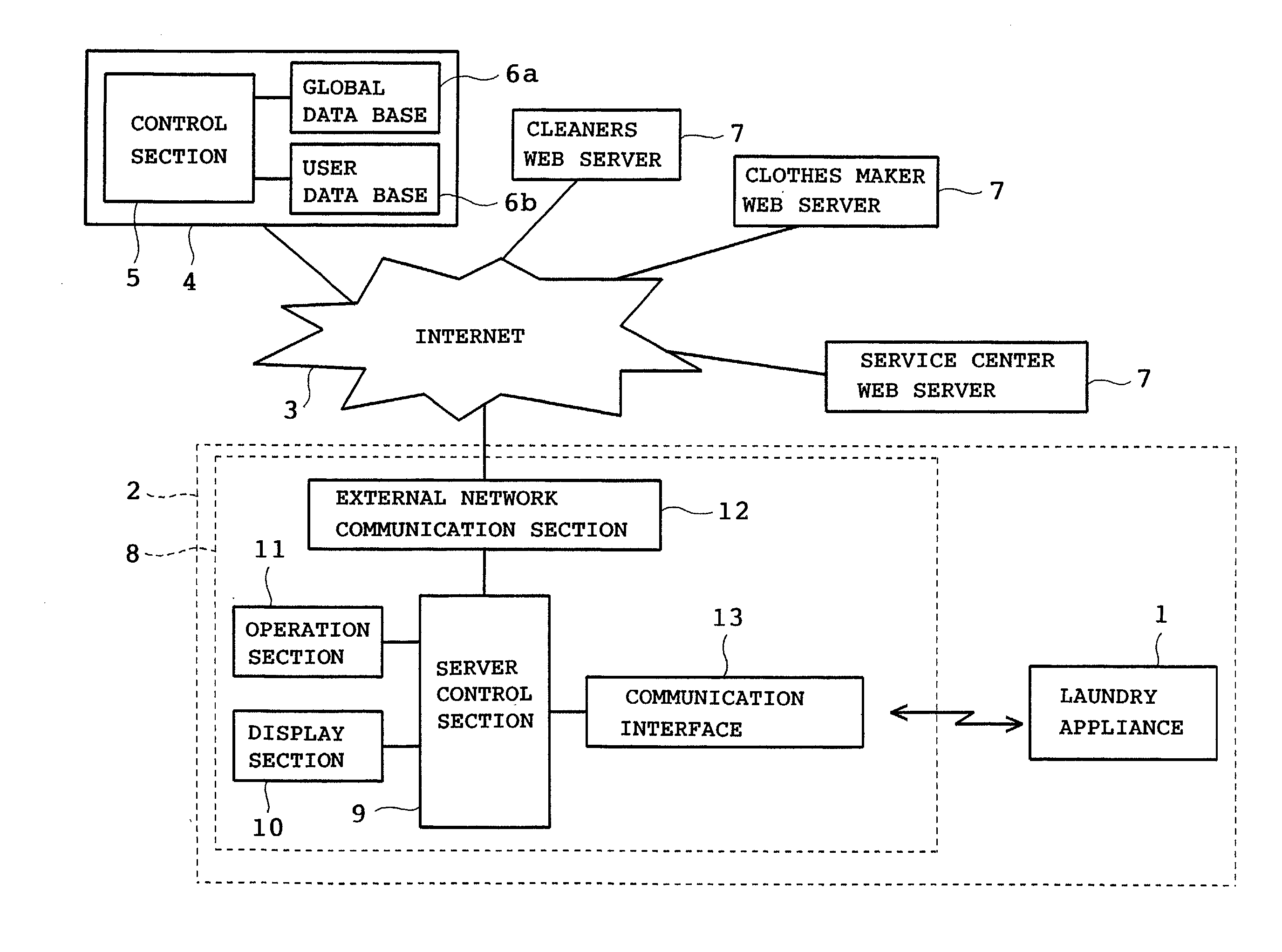
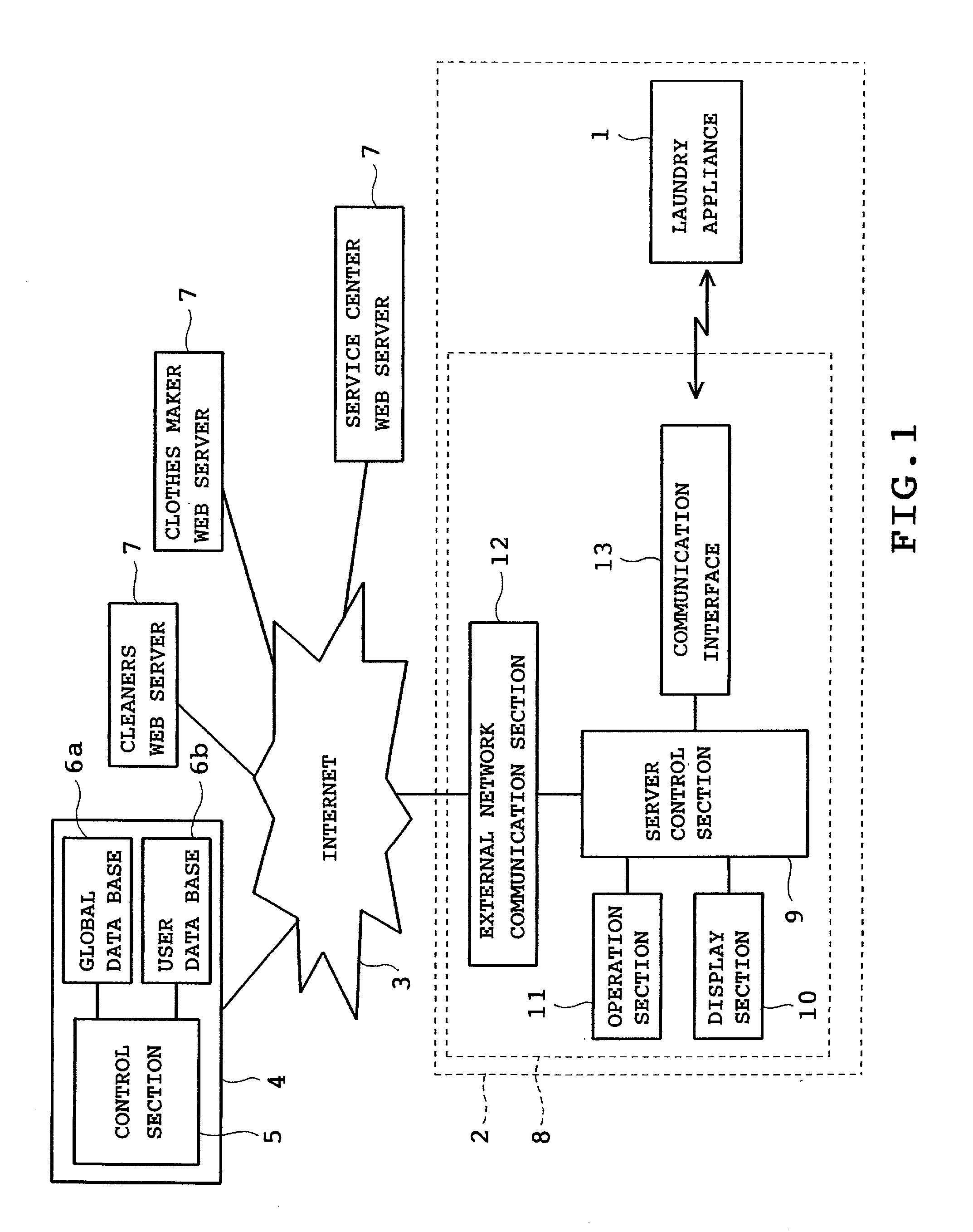
[0036] the invention will be described with reference to FIGS. 1 to 16. Referring to FIG. 1, a remote control system for a laundry appliance in accordance with the invention is schematically shown. The system controls a laundry appliance 1 installed in every house or office. A manufacturer of household electric appliances such as the laundry appliance 1 and a refrigerator opens a Web site on an Internet 3 serving as a communication network with a Web server 4. The Web server 4 remote controls the household electric appliances in every home or more particularly, the laundry appliance 1. Thus, the Web server 4 functions as a remote control device.
[0037] The Web server 4 includes a control section 5 serving as failure analyzing means for analyzing a failure and a global data base 6a and a user data base 6b both serving as storage means. The global data base 6a stores information required for the control of the laundry appliance 1, namely, information about operation of every type of al...
second embodiment
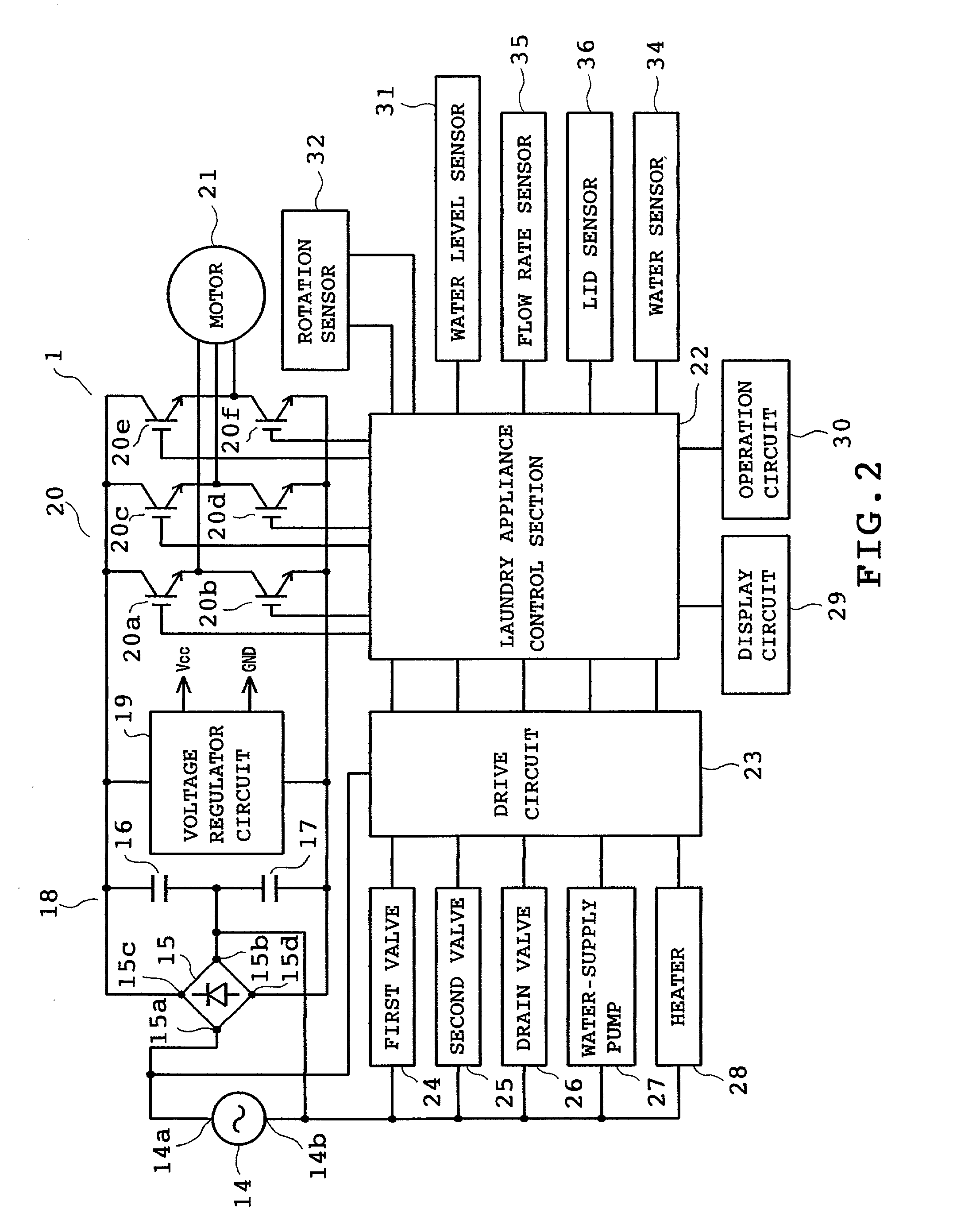
[0070] FIG. 17 illustrates the invention. The laundry appliance control section 22 includes an electric component drive unit 51 and a communication control unit 52. The electric component drive unit 51 includes an electric component drive section 54 and a power supply 55. The electric component drive section 54 has a function of controlling the motor 21, first and second valves 24 and 25, drain valve 26, water supply pump 27 and heater 28 on the basis of detection signals from various sensors. The communication control unit 52 includes a communication operation section 56 and a power supply section 57. The communication operation section 56 has a function of communicating with the home server 8, a function of controlling the display circuit 29, the operation circuit 30 and a power supply interrupter 62 which will be described later. The communication operation section 56 is connected to the electric component drive section 54. The power supply sections 55 and 57 are connected via el...
third embodiment
[0072] FIG. 18 illustrates the invention. An electromagnetic valve 45 is provided between a water service pipe and a faucet 33. The electromagnetic valve 45 is controlled by the control section 22 of the laundry appliance 1. When the test program, "E5-T1" corresponding to the abnormal condition in the water supply system is transmitted to the laundry appliance 1, the control section 22 drives the electromagnetic valve 45 and then carries out detection by means of the water sensor 34. Based on a result of detection by the water sensor 34, the Web server 4 determines whether the faucet 33 is left open.
[0073] When the Web server 4 determines that the abnormal condition is due to water leakage, the control section 22 immediately closes the electromagnetic valve 45. Consequently, damage due to the water leakage can be limited to minimum.
[0074] In each of the foregoing second and third embodiments, a portable terminal unit may be provided so as to access via the Internet 3 and home server...
PUM
 Abstract
Description
Claims
Application Information
 - R&D
- Intellectual Property
- Life Sciences
- Materials
- Tech Scout
- Unparalleled Data Quality
- Higher Quality Content
- 60% Fewer Hallucinations
Browse by: Latest US Patents, China's latest patents, Technical Efficacy Thesaurus, Application Domain, Technology Topic, Popular Technical Reports.
© 2025 PatSnap. All rights reserved.Legal|Privacy policy|Modern Slavery Act Transparency Statement|Sitemap|About US| Contact US: help@patsnap.com


