
Adjustable-length end piece for a fastener drive tool

a technology of drive tool and adjustable length, which is applied in the field of end pieces, can solve the problems of increasing the shipping cost and increasing the overall weight of the drive tool and its components

Inactive Publication Date: 2002-04-11
ACUMENT INTPROP LLC
View PDF0 Cites 1 Cited by
  • Summary
  • Abstract
  • Description
  • Claims
  • Application Information

AI Technical Summary

Benefits of technology

[0009] An object of an embodiment of the present invention is to provide an end piece which has a length that can be varied easily.
[0011] Still another object of an embodiment the present invention is to provide a single end piece which can accommodate various length fasteners thereby reducing the overall weight of the end pieces which must be supplied with a drive tool.
[0013] Briefly, and in accordance with at least one of the foregoing objects, an embodiment of the present invention provides an improved end piece for a drive tool which delivers fasteners to a work piece. The end piece includes an upper end piece and a lower end piece. By inserting a spacer between the upper and lower end pieces, the length of the end piece can be adjusted to accommodate fasteners of varying lengths. The spacer can include one or more spacer components to allow for an even greater variety of end piece lengths. Portions of the upper end piece, spacer components and lower end piece are threaded to allow for easy adjustment of the end piece's length.

Problems solved by technology

One disadvantage of supplying multiple end pieces with each drive tool is that each additional end piece increases the overall weight of the drive tool and its components.
The increased weight makes the drive tool and its components more difficult to transport and increases shipping costs.
Another disadvantage of providing multiple end pieces is that additional material and manufacturing costs are incurred.
Not only does the manufacture of each end piece require the supply of additional steel, but each manufacturing step to form the end piece (e.g. machining, drilling etc.) adds to the production cost of each end piece.
During use, the end piece of a drive tool is generally subjected to substantial forces.
Still another disadvantage of providing multiple end pieces of different lengths is that if a portion of a particular sized end piece becomes worn or damaged, the entire end piece must be replaced.
Until the end piece is replaced, the drive tool cannot be used to drive that respective sized fastener.

Method used


Image

  • Adjustable-length end piece for a fastener drive tool
  • Adjustable-length end piece for a fastener drive tool
  • Adjustable-length end piece for a fastener drive tool

Examples


Embodiment Construction

[0028] While the invention may be susceptible to embodiment in different forms, there is shown in the drawings, and herein will be described in detail, specific embodiments with the understanding that the present disclosure is to be considered an exemplification of the principles of the invention, and is not intended to limit the invention to that as illustrated and described herein.

[0029] Shown in FIG. 3 is an end piece 40 which is in accordance with an embodiment of the present invention. The length of the end piece 40 can be easily varied to accommodate fasteners of varying lengths. Therefore, there is no need to supply multiple end pieces with the drive tool. Thus, the overall weight of the end piece components provided with the drive tool is reduced. Additionally, should a particular component become damaged, the component can be replaced without requiring replacement of the entire end piece.

[0030] The end piece 40 is configured for use in connection with a drive tool such as t...


PUM


Abstract

An adjustable end piece engagable with a drive tool and configured to deliver fasteners from the drive tool to a work piece. Assembly of the adjustable end piece can be varied by varying the assembly of the end piece components and thus varying the length of the end piece. The variation in the length of the end piece allows the end piece to accommodate fasteners of varying lengths.

Description

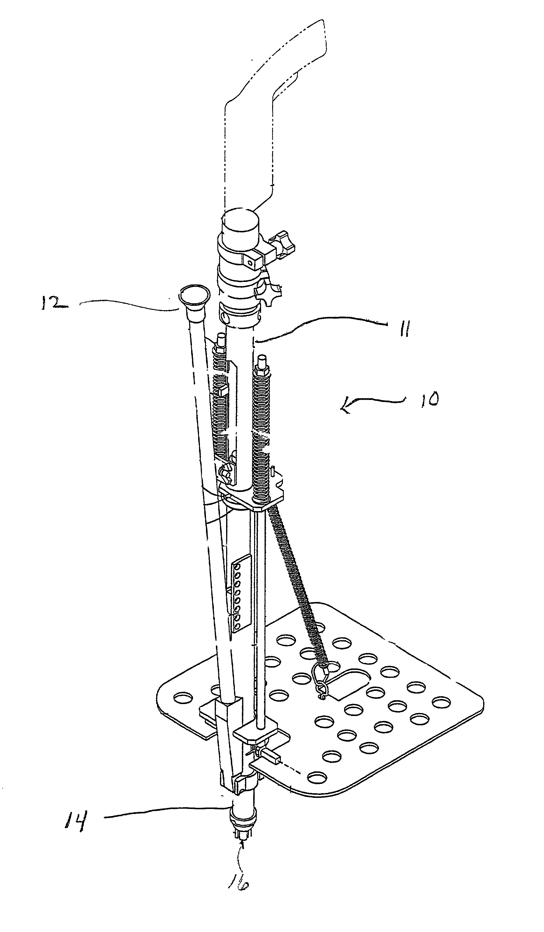
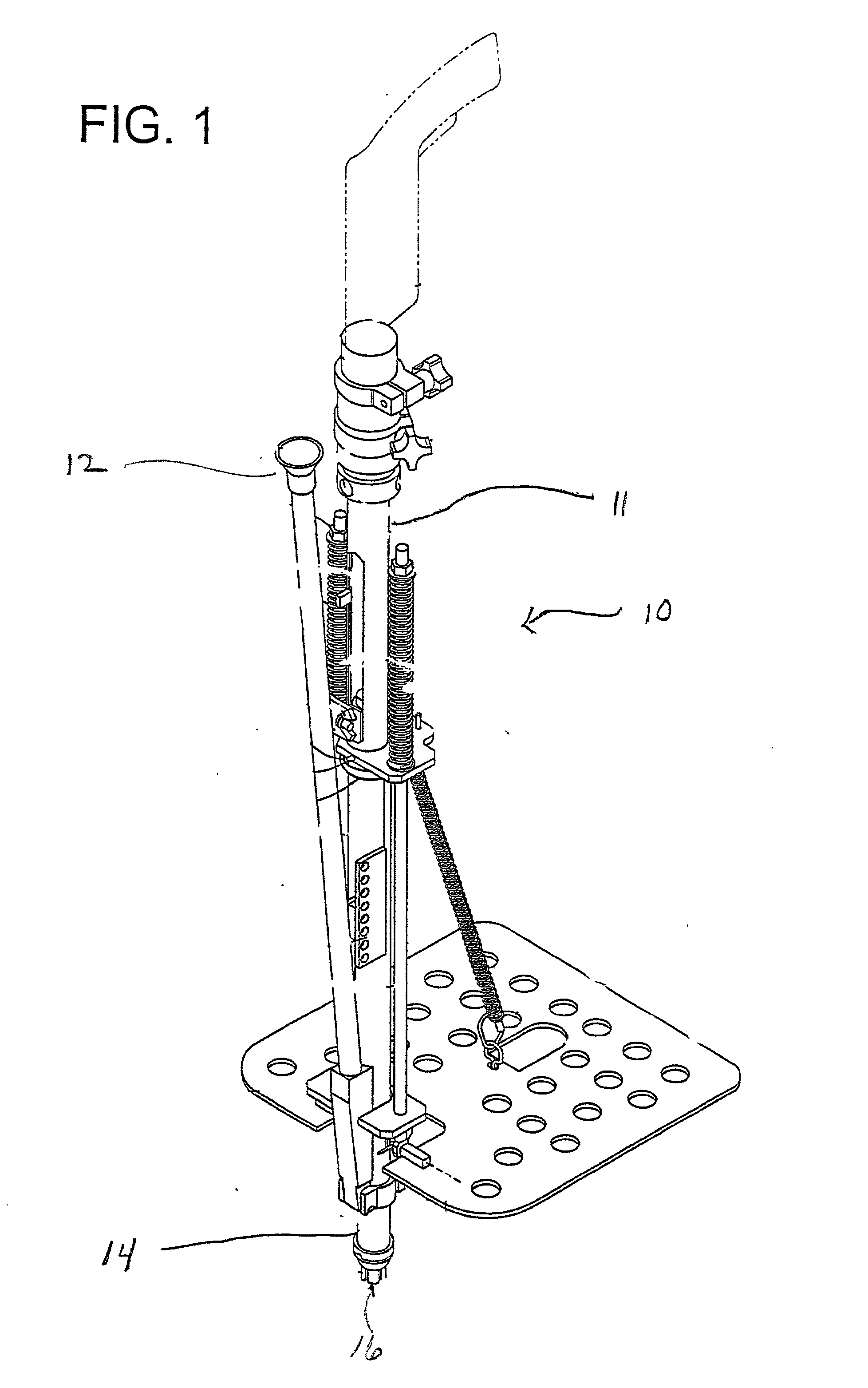
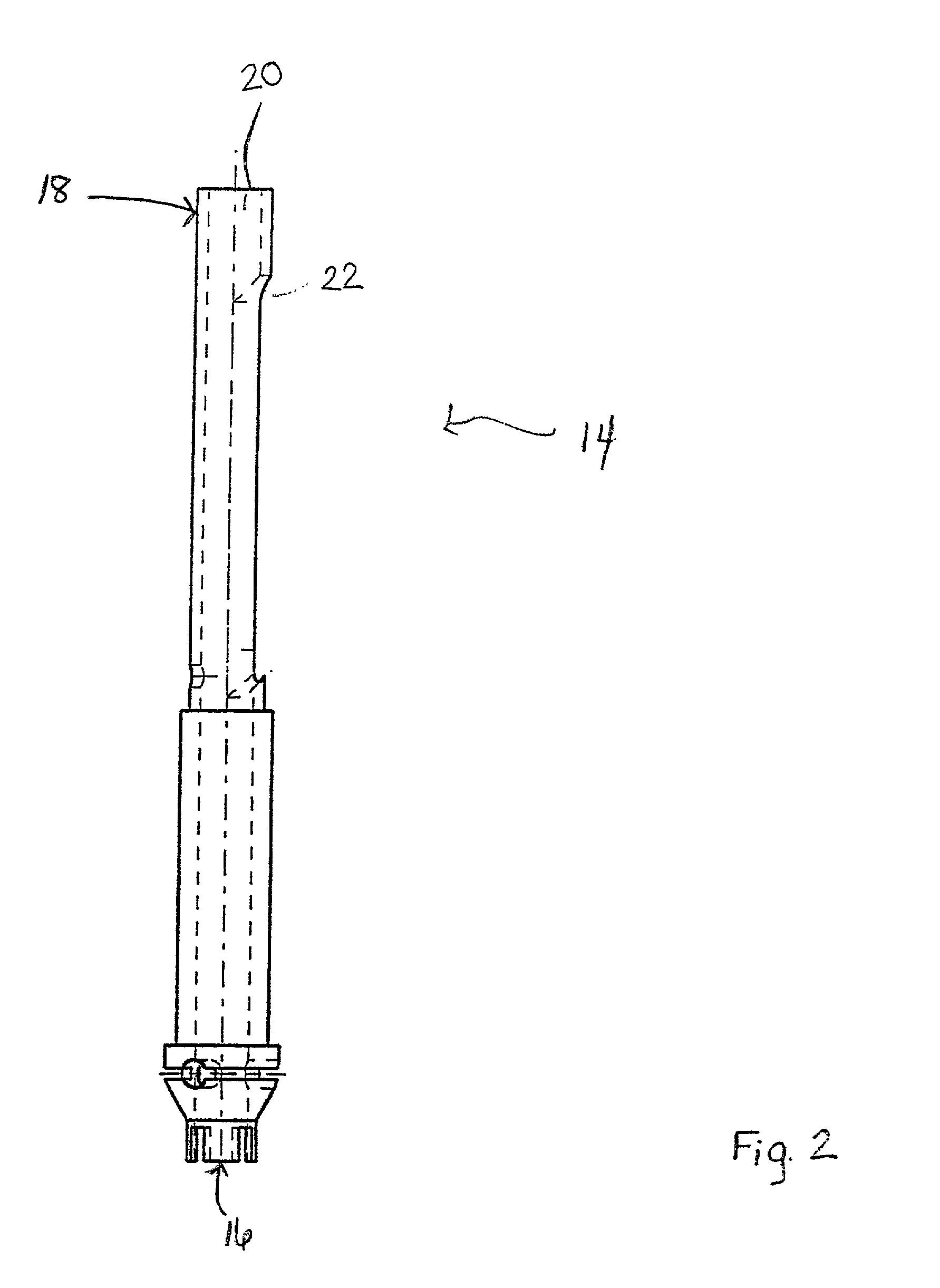
[0001] This invention generally relates to end pieces to be used in connection with tools for delivering fasteners to a work piece, and more specifically relates to an end piece which can be used with fasteners of different lengths.[0002] The end piece of the present invention can be used with a drive tool for driving fasteners into a workpiece. For example, the end piece of the present invention can be used with either of the drive tools described in U.S. patent application Ser. No. 09 / 680,761 or U.S. patent application Ser. No. 09 / 815,809 both of which are incorporated herein in their entirety by reference. The drive tool shown in FIG. 1 relates to U.S. patent application Ser. No. 09 / 815,809 and is an example of the drive tool in which the end piece of the present invention can be used. The drive tool 10 is configured to allow the operator to install a fasteners into a workpiece while he remains standing. The drive tool 10 includes a central housing 11, a funnel structure 12 locat...

Claims


Application Information

Patent Timeline
Patent Type & Authority Applications(United States)
IPC IPC(8): B25B21/00B25B23/04E04D5/12E04D15/04
CPCB25B21/002E04D2015/047E04D5/12B25B23/04
Inventor GOSS, DAVID C.KINGSBURY, JORDAN
Owner ACUMENT INTPROP LLC
Learn More