Parking aid system

a technology of parking aid and aid system, which is applied in the direction of braking system, pedestrian/occupant safety arrangement, instruments, etc., can solve the problems of high cost of conventional parking aid system, inability to instinctively tell whether the driver is going to park or not, and inability to meet the needs of drivers

Inactive Publication Date: 2002-04-11
HONDA MOTOR CO LTD
View PDF0 Cites 113 Cited by
  • Summary
  • Abstract
  • Description
  • Claims
  • Application Information

AI Technical Summary

Problems solved by technology

Thus, the conventional parking aid system suffers from high costs and the time required for parking is undesirably long due to a long calculation time performed by the arithmetic unit.
Furthermore, if the driving operations required to move the vehicle along the recommended trajectory become complicated, the driver

Method used


Image

  • Parking aid system
  • Parking aid system
  • Parking aid system

Examples


first embodiment

[0107] the present invention is explained below with reference to FIGS. 1 to 11.

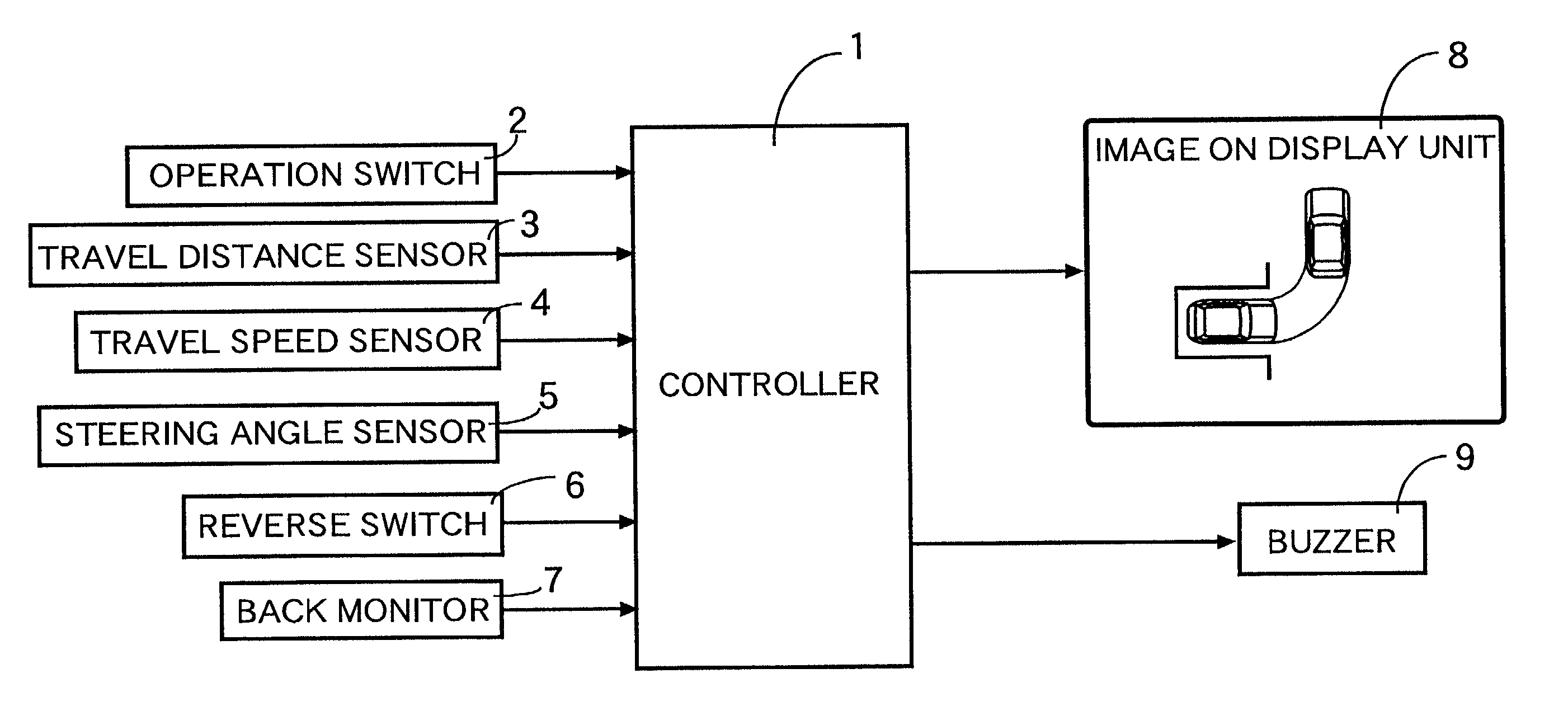
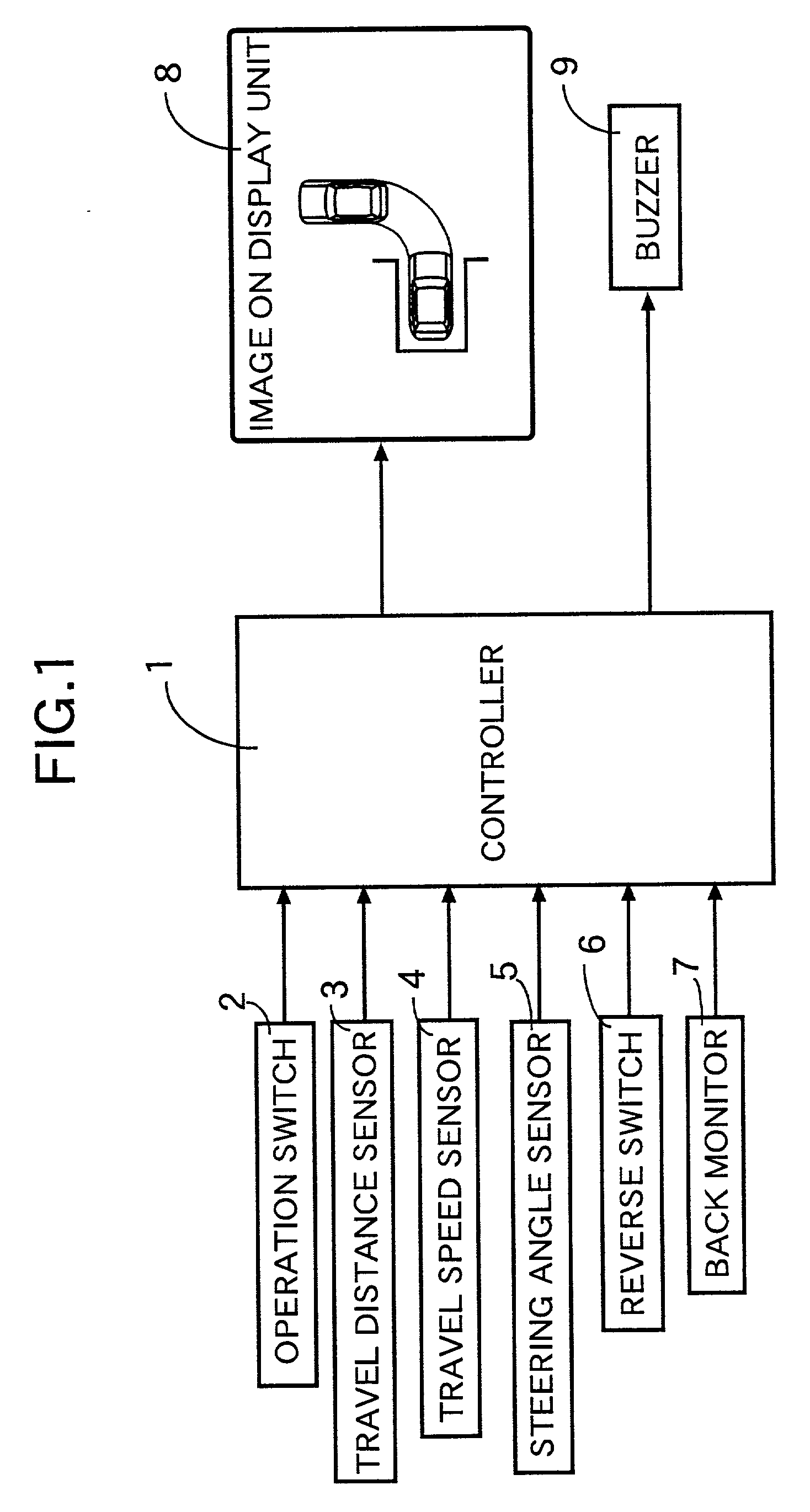
[0108] As shown in FIG. 1, a parking aid system mounted in a four wheel vehicle has a controller 1 including a microcomputer. An operation switch 2, a travel distance sensor 3, a travel speed sensor 4, a steering angle sensor 5, a reverse switch 6, a back monitor 7, a display unit 8, and a buzzer 9 are connected to the controller 1.

[0109] The operation switch 2 comprises a power switch, with which a driver switches on / off the power to the parking aid system, and a parking mode selection switch. The parking mode selection switch selects from three parking modes, that is `left reverse parking mode`, `right reverse parking mode` and `left parallel parking mode`. The parking mode selection switch is either formed from three switches so as to correspond to the three parking modes or is formed from one switch so that the three parking modes are switched in turn by pressing the one switch. Alternatively, the op...

second embodiment

[0137] the present invention is explained below with reference to FIGS. 12 to 18.

[0138] In the above-described first embodiment, when left reverse parking is performed, the subject vehicle travels forward in a straight manner from the start position to the reverse starting position. In the second embodiment, the subject vehicle travels forward and to the right from the start position to the reverse starting position. The state at the start position is the same as that of the first embodiment shown in FIG. 4, and FIG. 12 illustrates a state where the subject vehicle has traveled forward and to the right from the start position. As the subject vehicle travels forward and to the right from the start position, the subject vehicle position is calculated based on the distance traveled detected by the travel distance sensor 3 and the steering angle detected by the steering angle sensor 5. The expected parking position is calculated when the subject vehicle is reversed with the maximum stee...

third embodiment

[0156] the present invention is explained below with reference to FIGS. 19 to 22.

[0157] In the third embodiment of the present invention, when left reverse parking is carried out, the subject vehicle travels forward and to the right from a start position to a reverse starting position in the same manner as in the above-described second embodiment. The course along which the subject vehicle moves from the start position to the reverse starting position is the same as that in the second embodiment illustrated in FIGS. 12 and 13.

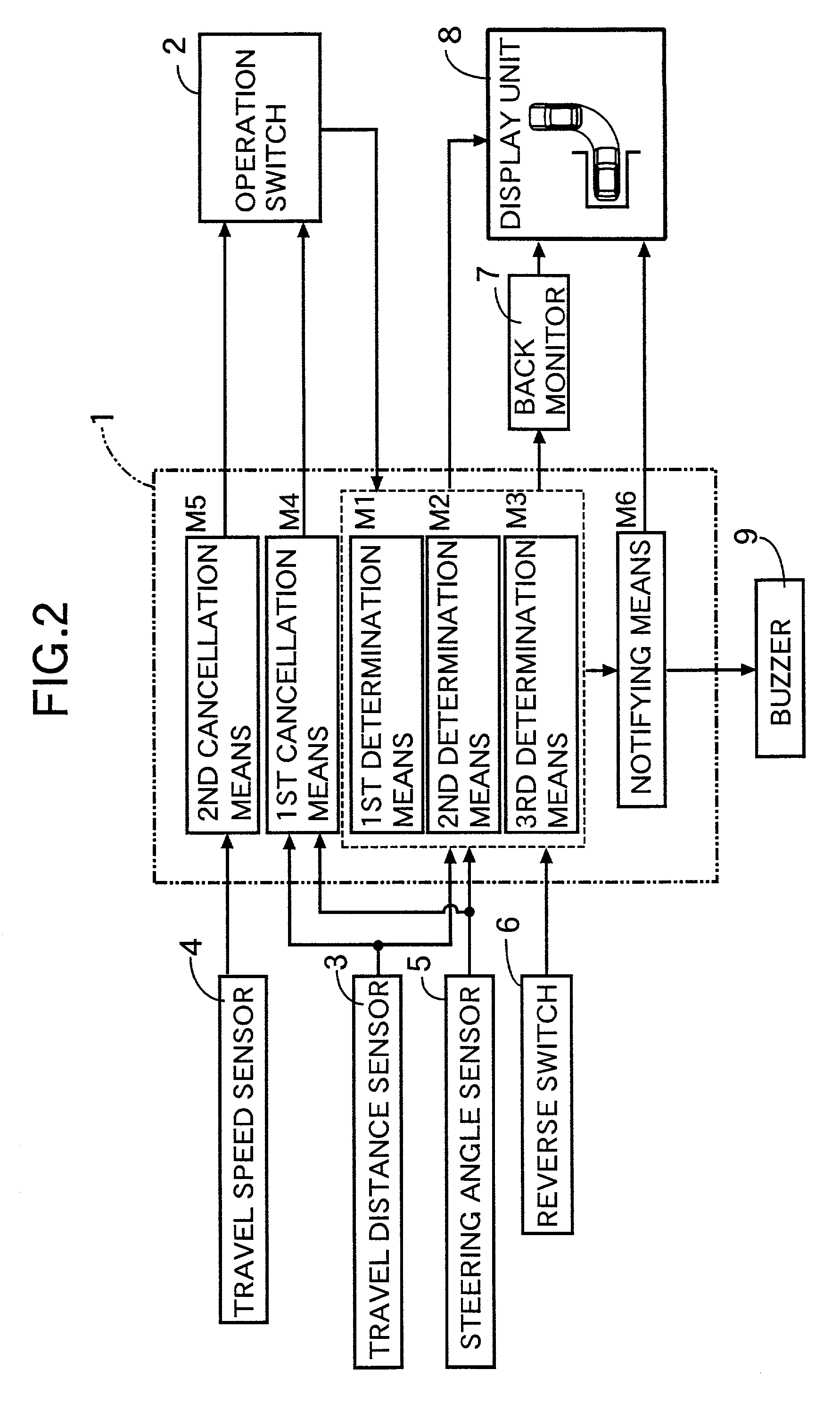
[0158] As shown in FIG. 13, when the subject vehicle reaches a correct reverse starting position, the first determination means M1, and the second determination means M2, determine that the expected parking position displayed on the display unit 8 coincides with the target parking position, and the notifying means M6 notifies the driver by operation of the buzzer 9. The expected trajectory and the expected parking position at this point are those that are obtai...


PUM


Abstract

A parking aid system having a driver initially stop the subject vehicle alongside a target parking position so that a mark provided inside a door coincides with the central line of the target parking position when assisting the driver with left reverse parking. The subject vehicle is a predetermined distance away from an entrance of the target parking position, when the driver turns the operation switch ON. A display unit then displays the target parking position, the subject vehicle position, and an expected parking position. The expected parking position is set at a position that the subject vehicle reaches when reversing with the steering wheel turned fully to the left. Therefore, when the driver moves the subject vehicle forward to a position where the expected parking position coincides with the target parking position and reverses the subject vehicle from that position through 90° while turning the steering wheel fully to the left, the subject vehicle can reliably be guided to the target parking position.

Description

[0001] 1. Field of the Invention[0002] The present invention relates to a parking aid system for aiding a driver in carrying out reverse parking or parallel parking.[0003] 2. Description of the Related Art[0004] A conventional parking aid system is disclosed in Japanese Patent Application Laid-open No. 11-157404 that identifies a parking space according to surrounding obstructions which are detected by, for example, a camera, radar or corner sensor. The parking aid system then calculates a recommended trajectory or locus from the current position of the vehicle to the above-mentioned parking space. The recommended trajectory is displayed over a parking space image on a display unit so as to direct the driver to, for example, steer, brake, accelerate or shift gear, and thus parking is assisted.[0005] However, the above-mentioned conventional parking aid system requires not only various types of sensors such as cameras, radars and comer sensors for identifying a parking space, but als...

Claims


Application Information

Patent Timeline
IPC IPC(8): B60R21/00B60R1/00B60R11/02B62D15/02
CPCB60R1/00B60R2300/302B60R2300/305B60R2300/607B62D15/0275B60R2300/8086B60T2201/10B62D15/027B60R2300/806
Inventor SHIMIZU, YASUOOHYAMA, YASUHARUSAKAI, KATSUHIRO
Owner HONDA MOTOR CO LTD
Why Eureka
Try Eureka