
Laminator and laminating method for lamination to substrate

a technology of lamination and substrate, applied in the direction of diffusion transfer process, thermography, instruments, etc., can solve the problems of increasing the running cost of production, and reducing the efficiency of production

Inactive Publication Date: 2002-05-16
FUJIFILM HLDG CORP +1
View PDF0 Cites 27 Cited by
  • Summary
  • Abstract
  • Description
  • Claims
  • Application Information

AI Technical Summary

Benefits of technology

[0025] Therefore, a product can be obtained efficiently, because the cooler operates quickly to cool the substrate between stations of the heat / pressure roller and the peeler.

Problems solved by technology

Those elements cause complication of the construction, to lower efficiency in the production.
Furthermore, establishment of the clean environment absolutely requires spaces for setting the buffer zone and the peeler device in a clean room.
The equipment for the production becomes very costly.
Also, the clean room should be large itself, to increase a running cost for the production.
Another problem arises in the method of cutting the laminated material into portions associated with each of the glass substrates.
Bits or dust is likely to occur by the cutting operation, and sticks on the glass substrates to cause failure in the product.

Method used


Image

  • Laminator and laminating method for lamination to substrate
  • Laminator and laminating method for lamination to substrate
  • Laminator and laminating method for lamination to substrate

Examples


Embodiment Construction

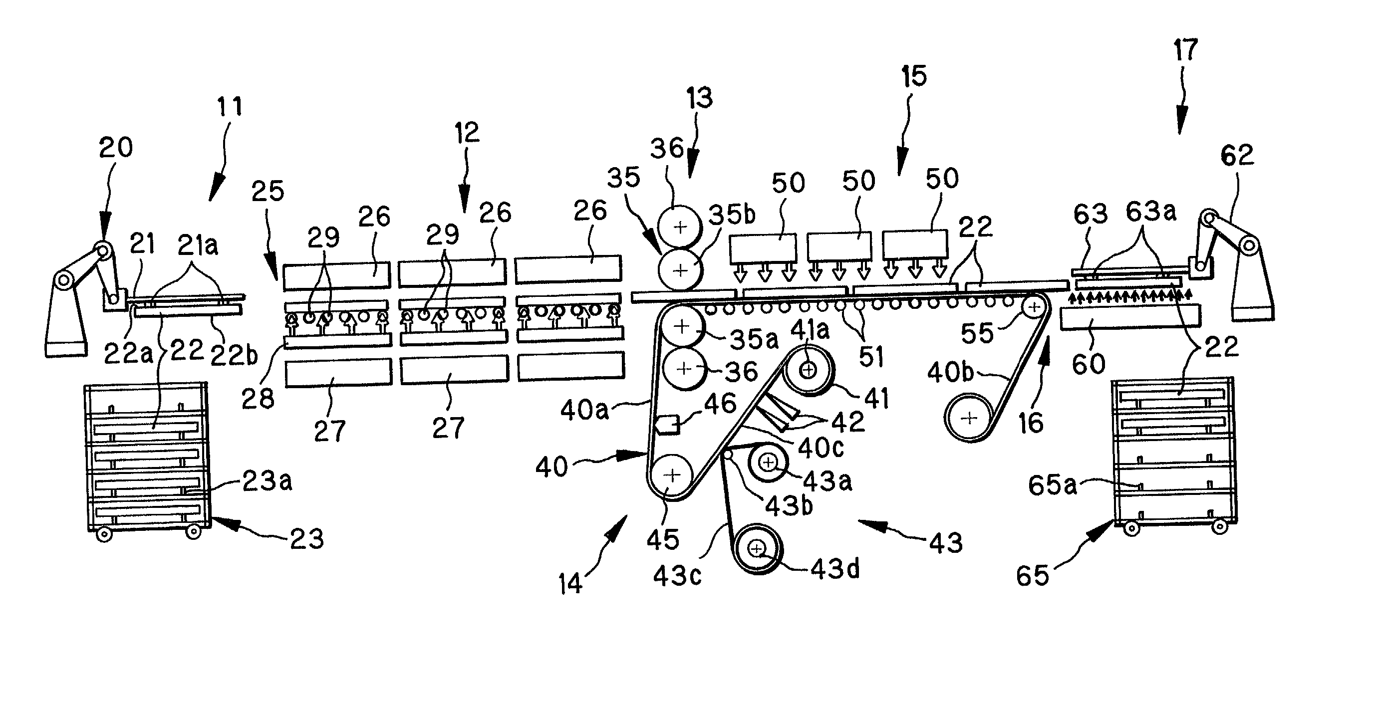
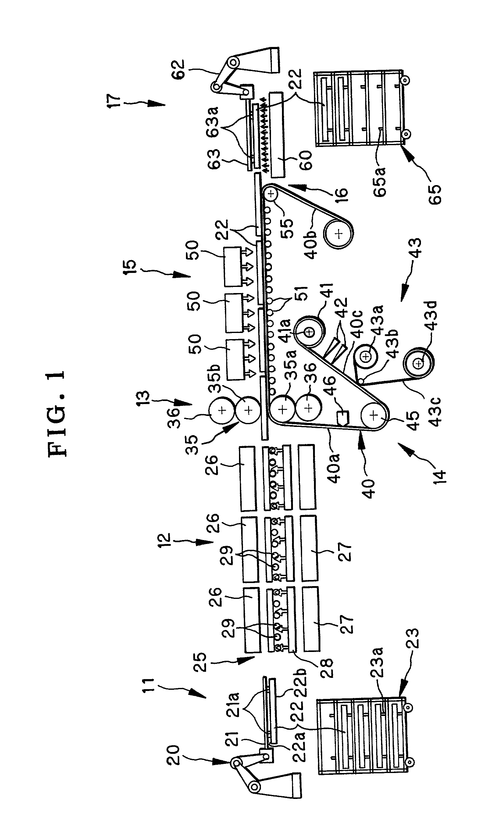
[0031] In FIG. 1, a laminator of the present invention is depicted. The laminator or a layer transferring device includes a supply transfer mechanism 11, a preheater 12, an attacher unit 13, a laminated material supply unit 14, a cooler 15 having a cooling fan or blower, a peeler 16, and an ejector 17.

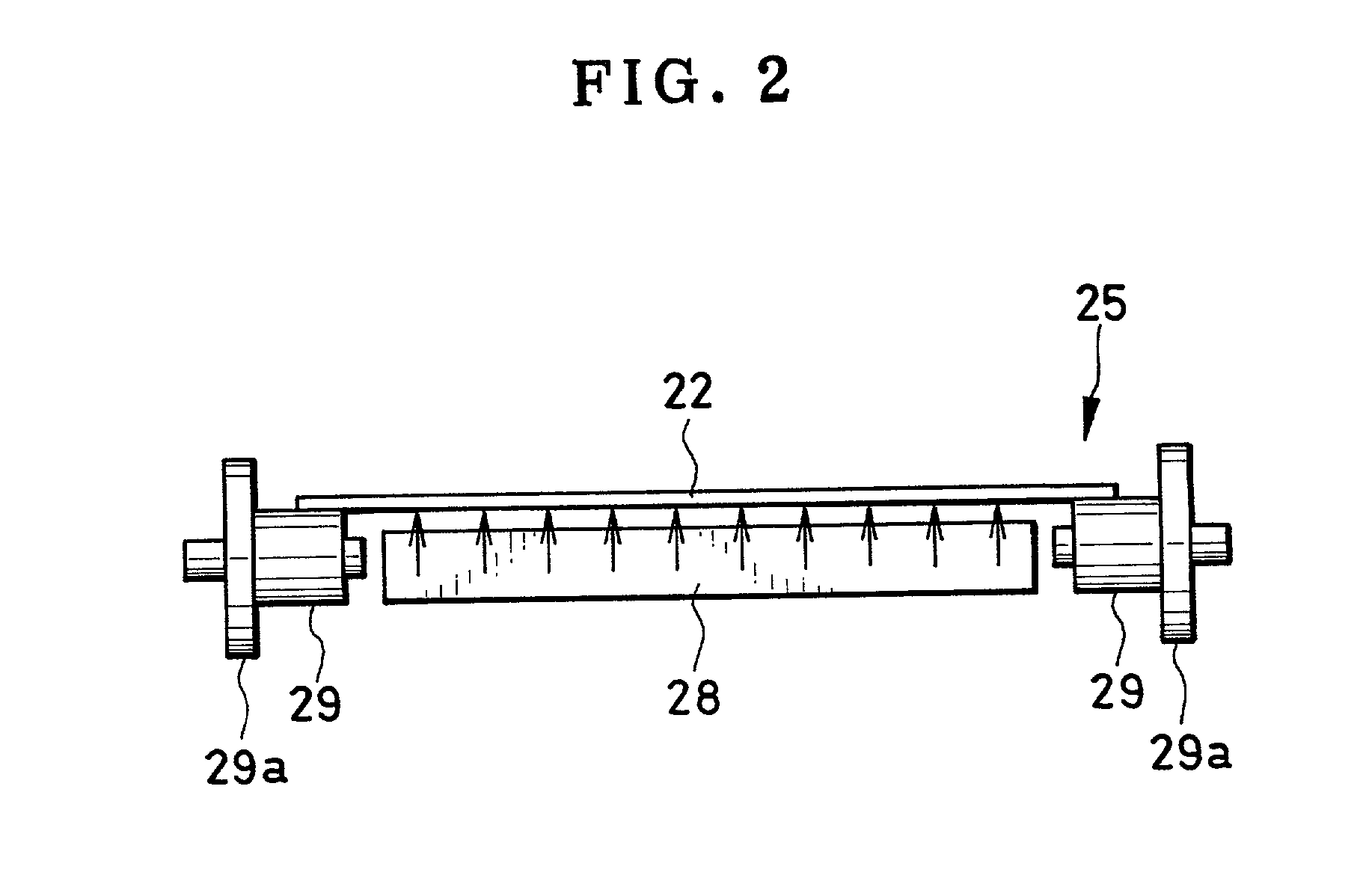
[0032] The supply transfer mechanism 11 includes a supply robot hand 20 of an articulated robot type. A hand body 21 of the supply robot hand 20 includes suction pads 21a. A glass substrate 22 has a back surface 22a, which is sucked or retained by the suction pads 21a, which keep the glass substrate 22 captured on the hand body 21. The glass substrate 22 also has a transfer receiving surface 22b which is reverse to the back surface 22a. A supply cassette 23 stores the glass substrate 22. The supply robot hand 20 takes the glass substrate 22 out of the supply cassette 23, and turns the glass substrate 22 by half a rotation to direct the transfer receiving surface 22b downwards, before t...


PUM

PropertyMeasurementUnit
temperatureaaaaaaaaaa
diameteraaaaaaaaaa

Abstract

A laminator for lamination to a substrate by use of continuous laminated material is provided. The laminated material includes a support, and a photosensitive transfer layer overlaid on the support. A heat / pressure roller attaches the laminated material to the substrate with heat and pressure with the transfer layer opposed to the substrate. A cooler cools the substrate with the laminated material. A peeler peels the support from the transfer layer on the substrate from the cooler, to transfer the transfer layer to the substrate.

Description

[0001] 1. Field of the Invention[0002] The present invention relates to a laminator and laminating method for lamination to a substrate. More particularly, the present invention relates to a laminator and laminating method for lamination to a substrate in which a product can be obtained efficiently and failure can be prevented reliably.[0003] 2. Description Related to the Prior Art[0004] A color filter for a liquid crystal display (LCD) panel is produced by photo lithography, in which a laminated sheet or plate having a photosensitive layer is exposed and developed for each of the three colors. To produce the laminated sheet or plate, a laminator is used for laminating or transferring a transfer layer to a glass substrate. At first, laminated material is prepared, including a support and the transfer layer overlaid thereon. The laminated material is a material of a shape of sheet or film. The support is a base film and has transmittance. The transfer layer is formed from photosensit...

Claims


Application Information

Patent Timeline
Patent Type & Authority Applications(United States)
IPC IPC(8): G03F7/004B32B37/08B32B37/18B32B38/10B32B43/00B41M5/26C09J1/00G03C1/74G03C8/00G03F7/16
CPCB32B37/025B32B37/08B32B37/18B32B38/10B32B43/006G03C1/74Y10T156/1339Y10T156/1064Y10T156/1749Y10T156/171Y10T156/1705Y10T156/12G03C8/00B41M5/26
Inventor NAGATE, HIROSHISUEHARA, KAZUYOSHIUEMATSU, SHINJI
Owner FUJIFILM HLDG CORP
Learn More