Seat sliding structure

a sliding structure and seat technology, applied in the direction of chairs, movable seats, roofs, etc., can solve the problems of synchronization mismatch, difficult to set a long back and forth traveling distance of seat 100 according to the conventional method, and not an eye-pleasing external appearance, etc., to achieve convenient transportation for passengers, convenient to get, and long traveling distance

Inactive Publication Date: 2002-05-16
SUZUKI MOTOR CORP
View PDF0 Cites 11 Cited by
  • Summary
  • Abstract
  • Description
  • Claims
  • Application Information

AI Technical Summary

Benefits of technology

0011] The object of the present invention is to provide a seat sliding structure which ensures satisfactory dimensional accuracy for installation of the seat and sliding rails and a long traveling distance in the back and forth direction, makes it easier for passengers to get on and off the vehicle floor and improves appearance.

Problems solved by technology

This imposes a restriction on the length of the sliding rail 101, so it has been difficult to set a long back and forth traveling distance of the seat 100 according to the conventional method.
This is certainly not an eye-pleasing external appearance.
However, the accuracy of mounting the sliding rails may be affected by the car body with increasing errors, so that a synchronization mismatch may occur.

Method used


Image

  • Seat sliding structure
  • Seat sliding structure
  • Seat sliding structure

Examples


Embodiment Construction

[0029] The following describes the embodiments according to the present invention with reference to drawings:

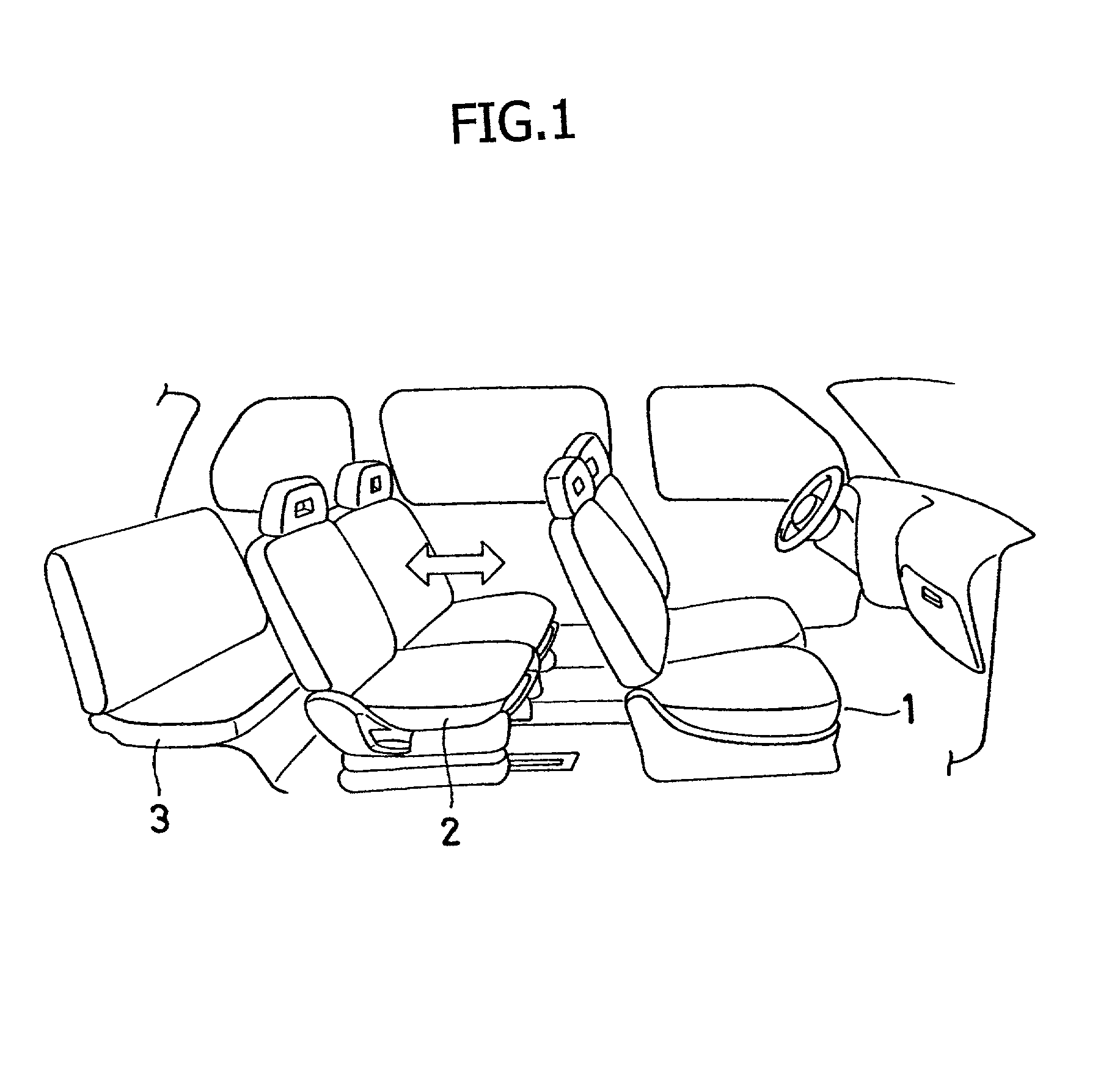
[0030] As illustrated in FIG. 1, multiple rows of seats 1, 2 and 3 are arranged inside the vehicle, and a longer traveling distance of the seat 2 in the second row is provided along the back and forth direction to allow the seat 2 in the second row to travel a long distance along the back and forth direction (arrow marked direction in FIG. 1). This ensures a larger trunk and seating space, and improves comfort to ride in. This way, a great variety of layouts may be provided for the interior of the vehicle.

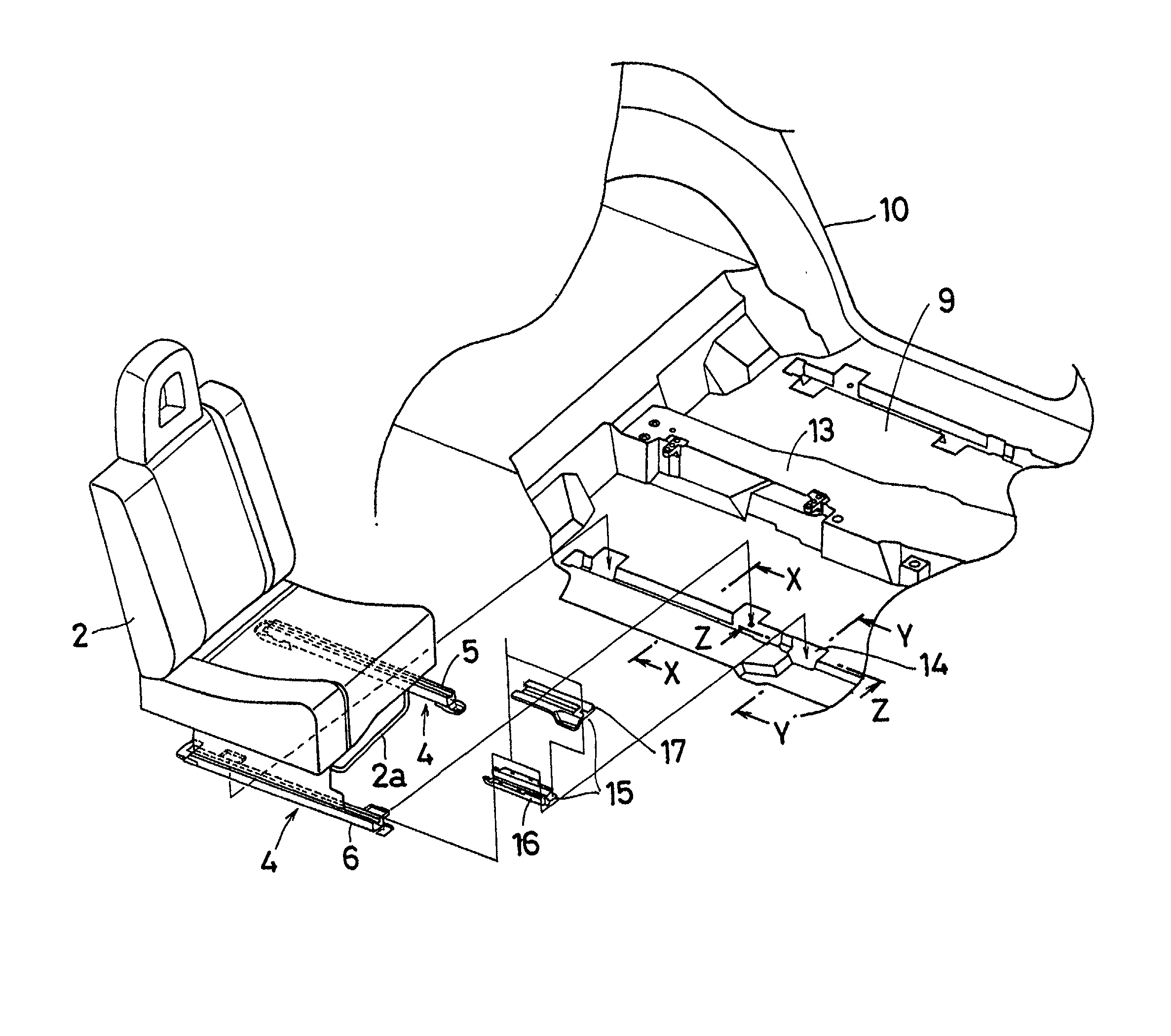
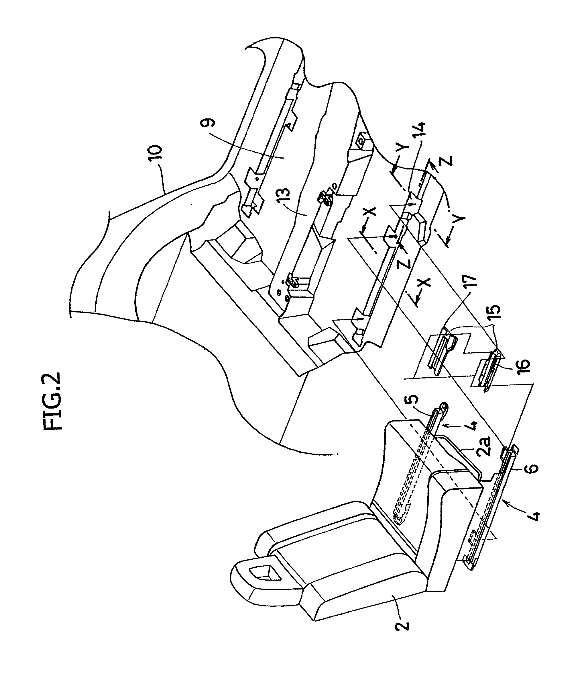
[0031] With reference to this embodiment, the following describes the example in which the sliding rail mechanism providing a long traveling distance in the back and forth direction is applied to the seat 2 of the second row. This mechanism is also applicable to other seats. Furthermore, the number of the seat rows can be changed in conformity to particular requirements.

[003...


PUM


Abstract

A sliding rail structure that allows the back and forth travel of the seat with respect to the vehicle floor surface, wherein the sliding rail 4 comprises a lower rail 8 and an upper rail 7 that is mounted on the seat in advance, and a groove 14 longer than the lower rail 8 is formed in the longitudinal direction of the floor panel 9 constituting the vehicle floor surface. The lower rail 8 and an extension 15 that continues from the lower rail 8 are installed in the groove 14, and the upper rail 7 slides inside the lower rail 8 and extension 15. This structure provides both satisfactory dimensional accuracy for installation of the seat and sliding rail as well as a long traveling distance in the longitudinal direction, facilitates passengers to get on and off the vehicle floor, and improves appearance.

Description

FIELD OF THE INVENTION AND RELATED ART STATEMENT[0001] The present invention relates to the structure of a seat sliding in the back and forth with respect to the floor surface of a vehicle.[0002] More particularly, the present invention relates to a slide rail structure designed to make a lower rail longer to provide a long traveling distance in the longitudinal direction in the vehicle. This structure is also applicable to a driver's seat, passenger seat and bench-formed seat in addition to a split type rear seat.[0003] To prevent synchronization errors of the slide rails 101 for a normal seat 100, the sliding rails 101 are mounted on the seat 100 while mounting dimensional accuracy is maintained with a jig, as illustrated in FIGS. 9 (a) and (b). Then the seat 100 provided with the sliding rails 101 is brought into the vehicle through the door opening thereof, and the seat 100 is locked on a floor panel 102 through the sliding rail 101.[0004] Furthermore, the sliding rail 101 is lo...

Claims


Application Information

Patent Timeline
Patent Type & Authority Applications(United States)
IPC IPC(8): B60N2/06B60N2/015B60N2/07B62D25/20
CPCB60N2/015B60N2/0715B60N2/0705B60N2/0725
Inventor FURUKAWA, AKIRA
Owner SUZUKI MOTOR CORP
Why Eureka
Try Eureka