Elevator drive machinery and elevator

a technology of drive machinery and elevators, applied in elevators, mine lifts, transportation and packaging, etc., can solve the problems of uneven force of parallel ropes, so as to reduce the turning radius of the rope passing.

Active Publication Date: 2020-03-05
KONE CORP
View PDF0 Cites 2 Cited by
  • Summary
  • Abstract
  • Description
  • Claims
  • Application Information

AI Technical Summary

Benefits of technology

[0011]The object of the invention is to provide a solution which is improved in terms of rope tension equalization of elevator ropes to be driven by a drive machinery. An object is particularly to alleviate one or more of the above defined drawbacks of prior art and / or problems discussed or implied elsewhere in the description. Solutions are presented, inter alia, by which an elevator can be achieved which has reduced variation of tension between individual ropes. Solutions are presented, inter alia, whereby this can be achieved even though the elevator has one or plurality of the following: long travel distance, low amount of slip, small diameter of the traction sheave and 2:1 suspension, low head room.
[0012]It is brought forward a new drive machinery for an elevator, the drive machinery comprising a rotatable drive sheave for driving plurality of ropes of the elevator, and a motor for rotating the drive sheave; the drive sheave comprising a drive sheave body rotatable around a rotational axis; and a plurality of rim arrangements mounted on the drive sheave body side by side in direction of said rotational axis, each said rim arrangement defining a circular outer rim for transmitting traction to a rope, in particular on which circular outer rim a rope can be placed to rest, said circular outer rims being coaxial with each other. The diameter of the circular outer rim of one or more of said rim arrangements is individually adjustable (i.e. without changing diameters of the rims of the other rim arrangements) for enlarging or reducing the turning radius of a rope passing around the circular outer rim in question.
[0013]With this solution, it is possible to adjust the speed of a particular rope relative to the other ropes of the elevator by which speed the rope passes around the drive sheave from one side of it to the other side of it. With the solution described, a tension difference, such as a tension difference generated by car position change, between said particular rope and other ropes, can be eliminated.

Problems solved by technology

Traction sheave elevators are prone to having more or less uneven rope forces.
Ideally, parallel ropes would have equal forces, but in practice rope force differences exist in the elevator due to non-idealities, such as rope thickness variation, rope stiffness variation, rope coating thickness variation or rope groove diameter variation.
This will generate unevenness in forces of parallel ropes.
Especially high friction ropes, such as ropes having a polymer coating, are easily subjected to large force variations due to their small slip on the drive sheave.
Large rope force variations occurring on every roundtrip cause excessive fatigue loads on load bearing components, such as rope fixings, ropes themselves and guide shoes.
They also cause ride comfort problems, increase pulley wear rate and reduce rope lifetime.
Problems of rope force variation may also be faced with ropes engaging with positive engagement with the drive sheave.
A drawback of these known solutions is that they allow only very limited range of movement of the rope ends.
It has been noticed that with high friction ropes, such as ropes having a polymer coating, there is little or virtually no slip between ropes and the traction sheave, so the travel differences are hardly compensated by slip unlike in the case of steel ropes.
Different elongations cause uneven rope forces especially when the car or the counterweight is approaching the top of the hoistway, because in this case suspension ropes are short and their stiffness is high.
It has also been noticed that rope travel differences are prone to accumulate with each rotation of the traction sheave.
Long travel distance of the elevator, small traction sheave and 2:1 suspension increase the number of rotations of the sheave and worsen the problem.
It has therefore been noticed a drawback that the ability of prior solutions to equalize tension is the most problematic in elevators which have one or more of the following: long travel distance, low amount of slip, small diameter of the traction sheave and 2:1 suspension, low head room.

Method used


Image

  • Elevator drive machinery and elevator
  • Elevator drive machinery and elevator
  • Elevator drive machinery and elevator

Examples


Embodiment Construction

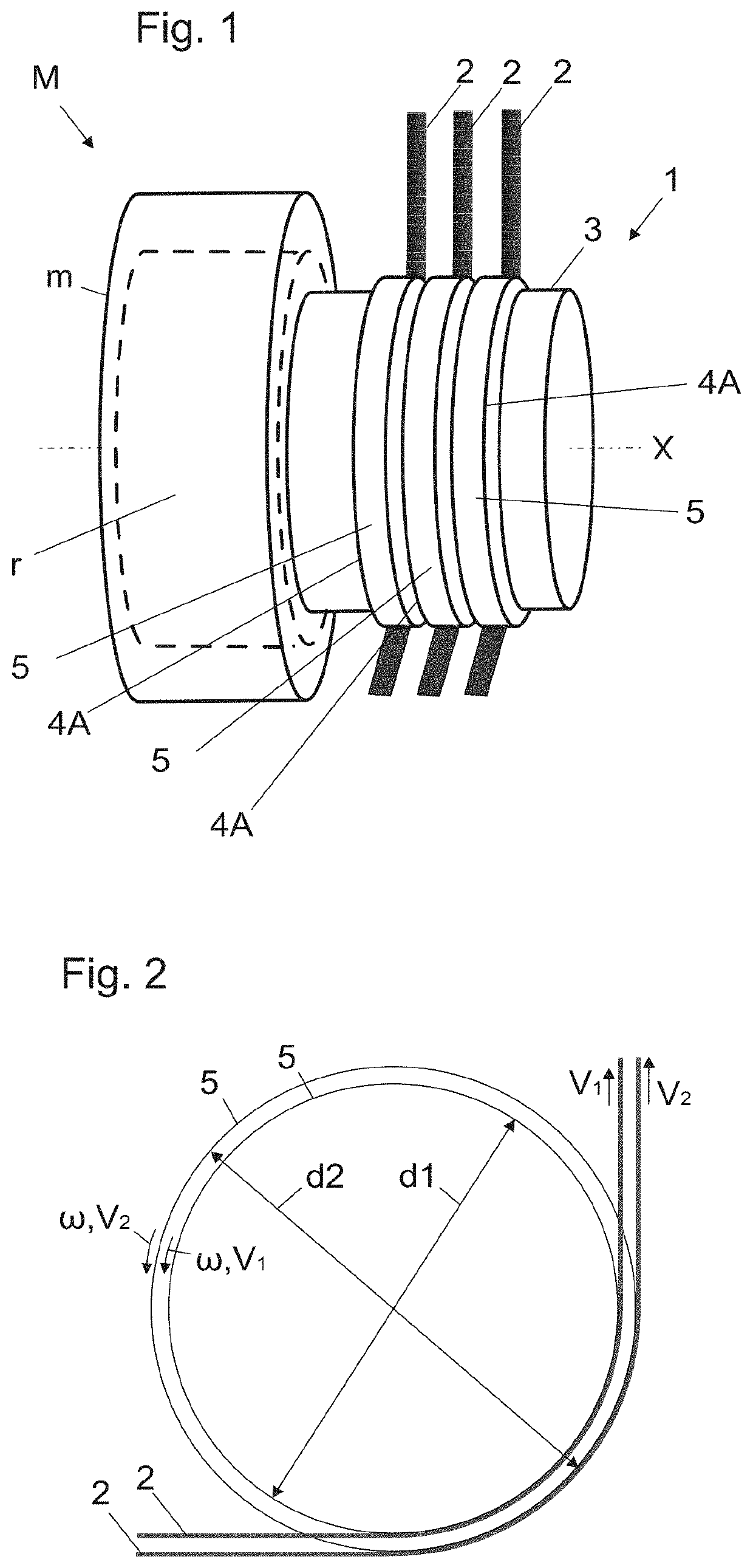
[0083]FIG. 1 illustrates a drive machinery M for an elevator according to a preferred embodiment. The drive machinery M comprises a rotatable drive sheave 1 for driving plurality of ropes 2 of the elevator, and a motor m for rotating the drive sheave 1. The motor m is preferably an electric motor. The drive sheave 1 comprises a drive sheave body 3 rotatable around a rotational axis X. The drive sheave 1 moreover comprises a plurality of rim arrangements 4A mounted on the drive sheave body 3 side by side in direction of said rotational axis X, each said rim arrangement 4A defining a circular outer rim 5 for transmitting traction to a rope 2, and on which circular outer rim 5 a rope can be placed to rest. The outer rims 5 of the rim arrangements 4A are coaxial with each other. Said rotational axis X is a rotational axis of the circular outer rims 5.

[0084]The drive machinery M is suitable for exerting traction via the rim arrangements 4A on the ropes 2 passing around them. In FIG. 1, t...


PUM


Abstract

The invention relates to a drive machinery for an elevator, the drive machinery comprising a rotatable drive sheave for driving plurality of ropes of the elevator, and a motor for rotating the drive sheave; the drive sheave comprising a drive sheave body rotatable around a rotational axis; and plurality of rim arrangements mounted on the drive sheave body side by side in direction of said rotational axis, each said rim arrangement defining a circular outer rim for transmitting traction to a rope, said circular outer rims being coaxial with each other. The diameter of the circular outer rim of one or more of said rim arrangements is individually adjustable for enlarging or reducing the turning radius of a rope passing around the circular outer rim in question. The invention also relates to an elevator comprising said drive machinery.

Description

RELATED APPLICATIONS[0001]This application claims priority to European Patent Application No. 18192683.3 filed on Sep. 5, 2018, the entire contents of which are incorporated herein by reference.FIELD OF THE INVENTION[0002]The invention relates to an elevator drive machinery and an elevator utilizing the drive machinery. The elevator is preferably an elevator for transporting passengers and / or goods.BACKGROUND OF THE INVENTION[0003]Elevators typically comprise a drive sheave and a roping comprising ropes connected with the elevator car and passing around the drive sheave. Via the ropes, traction force can be transmitted from the drive sheave to the car. Thereby, car movement can be achieved and controlled by the drive sheave. The drive sheave can be rotatable by an electric motor, for example.[0004]The ropes driven by the drive sheave are typically connected on one side of the drive sheave with the elevator car and on the other side with a counterweight.[0005]Traction sheave elevator...

Claims


Application Information

Patent Timeline
Patent Type & Authority Applications(United States)
IPC IPC(8): B66B15/04B66B11/08B66B7/10B66B11/04
CPCB66B11/08B66B15/04B66B11/043B66B7/10B66B11/008
Inventor HELENIUS, JUHAPELTO-HUIKKO, RAIMO
Owner KONE CORP
Why Eureka
Try Eureka