Cross beam structure for large-format optical fiber laser cutting machine

A fiber laser and cutting machine technology, applied in laser welding equipment, welding equipment, metal processing equipment, etc., can solve the problems of reduced cutting precision and high precision requirements, and achieve the effect of fast running speed, high parameters and stable operation

Active Publication Date: 2019-12-31
WUHAN PENTA CHUTIAN LASER EQUIP
View PDF6 Cites 1 Cited by
  • Summary
  • Abstract
  • Description
  • Claims
  • Application Information

AI Technical Summary

Problems solved by technology

[0009] (7) For the market, the thickness of the cut plate is getting thicker and thicker, and the width of the processed plate is getting longer and wider. Many do not want to cut and then process, which leads to high precision requirements.
Howev

Method used


Image

  • Cross beam structure for large-format optical fiber laser cutting machine
  • Cross beam structure for large-format optical fiber laser cutting machine
  • Cross beam structure for large-format optical fiber laser cutting machine

Examples


Embodiment Construction

[0027] The following examples are used to illustrate the present invention, but are not intended to limit the scope of the present invention.

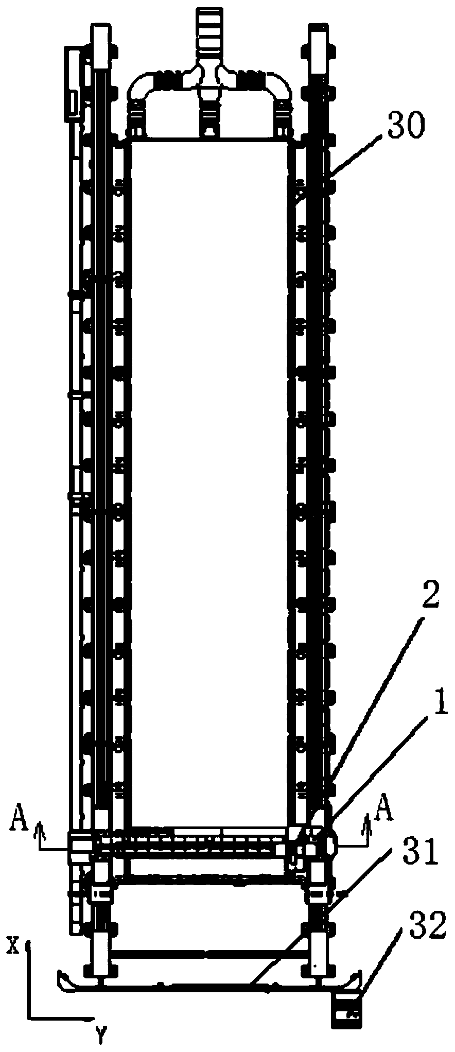
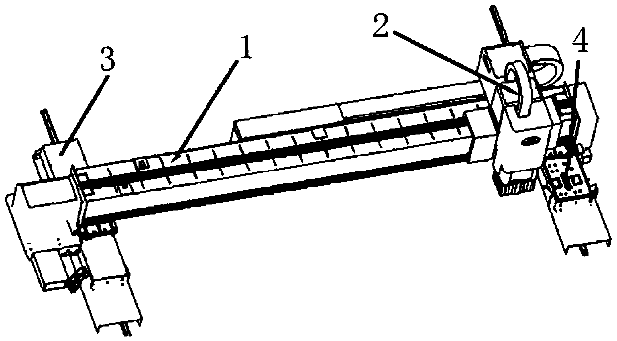
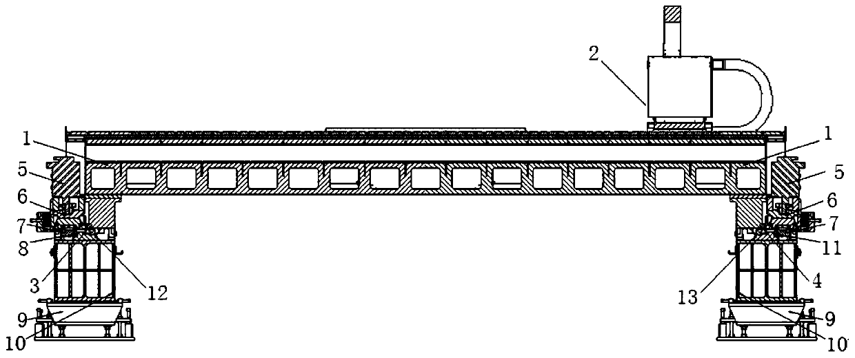
[0028] see Figure 1-8 , a beam structure for a large-format fiber laser cutting machine of the present invention, including a beam and a Z-axis, the Z-axis is installed on the rolling linear guide rail of the beam, and the two ends of the beam are respectively installed on the left beam moving slide and the right beam moving slide On the seat, the left crossbeam moving slide and the right crossbeam moving slide are respectively installed on the rolling linear guide rail of the base, the motor is connected with the reducer, the gear is connected with the reducer, the rack is meshed with the gear, the rack is on the bed, and the bed is fixed On the base, the motor drives the left beam moving slide and the right beam moving slide to move on the rack, and uses the base rolling linear guide to move in the direction of the X axis. The left ...


PUM


Abstract

The invention relates to a cross beam structure for a large-format optical fiber laser cutting machine. A Z axis is arranged on a cross beam rolling linear guide rail; two ends of a cross beam are arranged on a left cross beam movement sliding seat and a right cross beam movement sliding seat; the left cross beam movement sliding seat and the right cross beam movement sliding seat are arranged ona base rolling linear guide rail; a motor is connected with a speed reducer; a gear is connected with the speed reducer; a rack meshes with the gear and is arranged on a lathe bed; the lathe bed is fixed onto a base; the motor drives the left cross beam movement sliding seat and the right cross beam movement sliding seat to move on the rack by adopting the base rolling linear guide rail as an X-axis direction; and automatic floating adjustment systems are arranged in the left cross beam movement sliding seat and the right cross beam movement sliding seat. According to the cross beam structurefor the large-format optical fiber laser cutting machine provided by the invention, the optical fiber laser cutting machine is long in runnable stroke, stable to run, high in positioning accuracy, high in repositioning accuracy, high in runnable speed acceleration, high in other parameters, convenient to adjust, and capable of realizing high-accuracy cutting without manual intervention in the whole process.

Description

technical field [0001] The invention relates to an optical fiber laser cutting, in particular to a beam structure for a large-format optical fiber laser cutting machine. Background technique [0002] Laser cutting machines are used more and more in industry. Because the laser cutting machine has many characteristics such as fast processing speed, good processing quality, simple operation, strong applicability of processing plates and graphics, and convenient replacement of processed parts, it has been widely used in automobiles, rolling stock manufacturing, aviation, chemical industry, light industry, Industrial sectors such as electrical appliances and electronics, petroleum and metallurgy. However, in order to meet the needs of the market in various aspects, various requirements have been put forward for laser cutting machines in order to better meet the market needs. The application of laser cutting can be promoted in the following aspects: [0003] (1) With the develo...

Claims


Application Information

Patent Timeline
IPC IPC(8): B23K26/08B23K26/38
CPCB23K26/0876B23K26/38
Inventor 魏开松
Owner WUHAN PENTA CHUTIAN LASER EQUIP
Why Eureka
Try Eureka