Elevator drive machinery and elevator

a technology of drive machinery and elevators, which is applied in the direction of elevators, mine lifts, transportation and packaging, etc., can solve the problems of uneven rope force, large variation of rope force, and high friction ropes, such as ropes having a polymer coating, easily subject to large force variations

Active Publication Date: 2019-12-12
KONE CORP
View PDF0 Cites 1 Cited by
  • Summary
  • Abstract
  • Description
  • Claims
  • Application Information

AI Technical Summary

Benefits of technology

[0012]It is brought forward a new drive machinery for an elevator comprising a rotatable drive sheave for driving plurality of ropes of the elevator, the drive sheave comprising a central cylinder, which comprises a central axis around which the central cylinder is rotatable; plurality of circular rim members surrounding the central cylinder, each said rim member comprising an outer rim surface for engaging a rope. The drive sheave is arranged to exert traction via the circular rim members on the ropes passing around them. Said plurality of circular rim members includes one or more rotatably mounted circular rim members, each said rotatably mounted circular rim member being mounted, preferably via bearings, on the central cylinder rotatably around said central axis relative to the central cylinder and relative to one or more of the other circular rim members, and said drive sheave moreover comprises a control means for controlling rotation of each said rotatably mounted circular rim member relative to the central cylinder and relative to one or more of the other circular rim members. With the control means, it is possible to control transmission of force between the central cylinder and an individual rotatably mounted circular rim member. Hereby, a tension difference (which is generated by car position change) between a rope passing around said rotatably mounted circular rim member and ropes passing around the other circular rim members, can be eliminated.

Problems solved by technology

Traction sheave elevators are prone to having uneven rope forces.
Ideally, parallel ropes would have equal forces, but in practice rope force differences exist in the elevator due to non-idealities, such as rope thickness variation, rope stiffness variation, rope coating thickness variation or rope groove diameter variation.
Especially high friction ropes, such as ropes having a polymer coating, are easily subjected to large force variations due to their small slip on the drive sheave.
Large rope force variations occurring on every roundtrip cause excessive fatigue loads on load bearing components, such as rope fixings, ropes themselves and guide shoes.
They also cause ride comfort problems, increase pulley wear rate and reduce rope lifetime.
Problems of rope force variation may also be faced with ropes engaging with positive engagement with the drive sheave.
A drawback of these known solutions is that they allow only very limited range of movement of the rope ends.
It has been noticed that with high friction ropes, such as ropes having a polymer coating, there is little or virtually no slip between ropes and the traction sheave, so the travel differences are hardly compensated by slip unlike in the case of steel ropes.
Different elongations cause uneven rope forces especially when the car or the counterweight is approaching the top of the hoistway, because in this case suspension ropes are short and their stiffness is high.
Long travel distance of the elevator, small traction sheave and 2:1 suspension increase the number of rotations of the sheave and worsen the problem.
It has therefore been noticed a drawback that the ability of prior solutions to equalize tension is the most problematic in elevators which have one or more of the following: long travel distance, low amount of slip, small diameter of the traction sheave and 2:1 suspension, low head room.

Method used


Image

  • Elevator drive machinery and elevator
  • Elevator drive machinery and elevator
  • Elevator drive machinery and elevator

Examples


Embodiment Construction

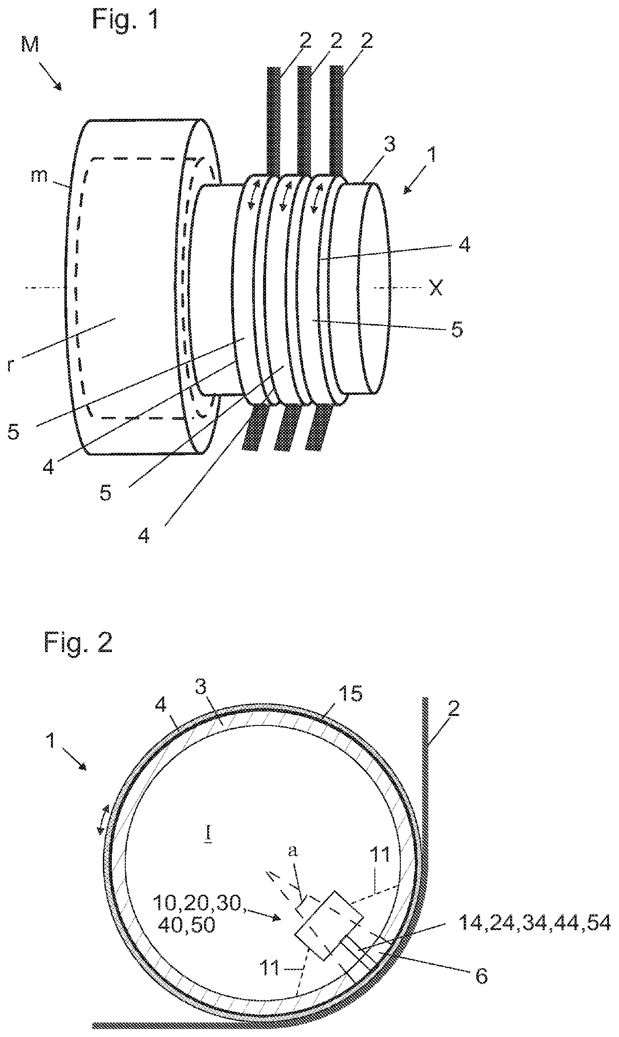
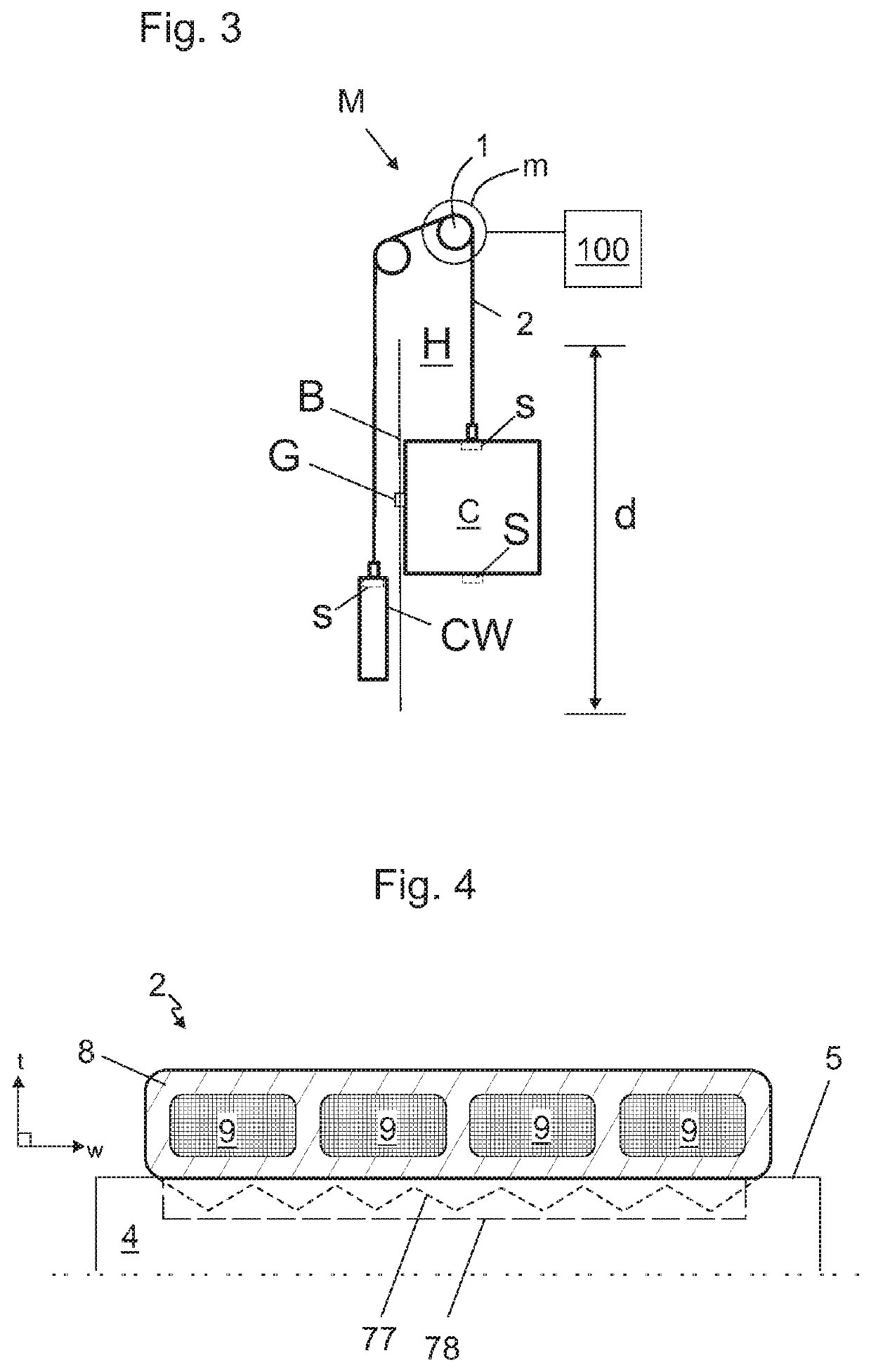
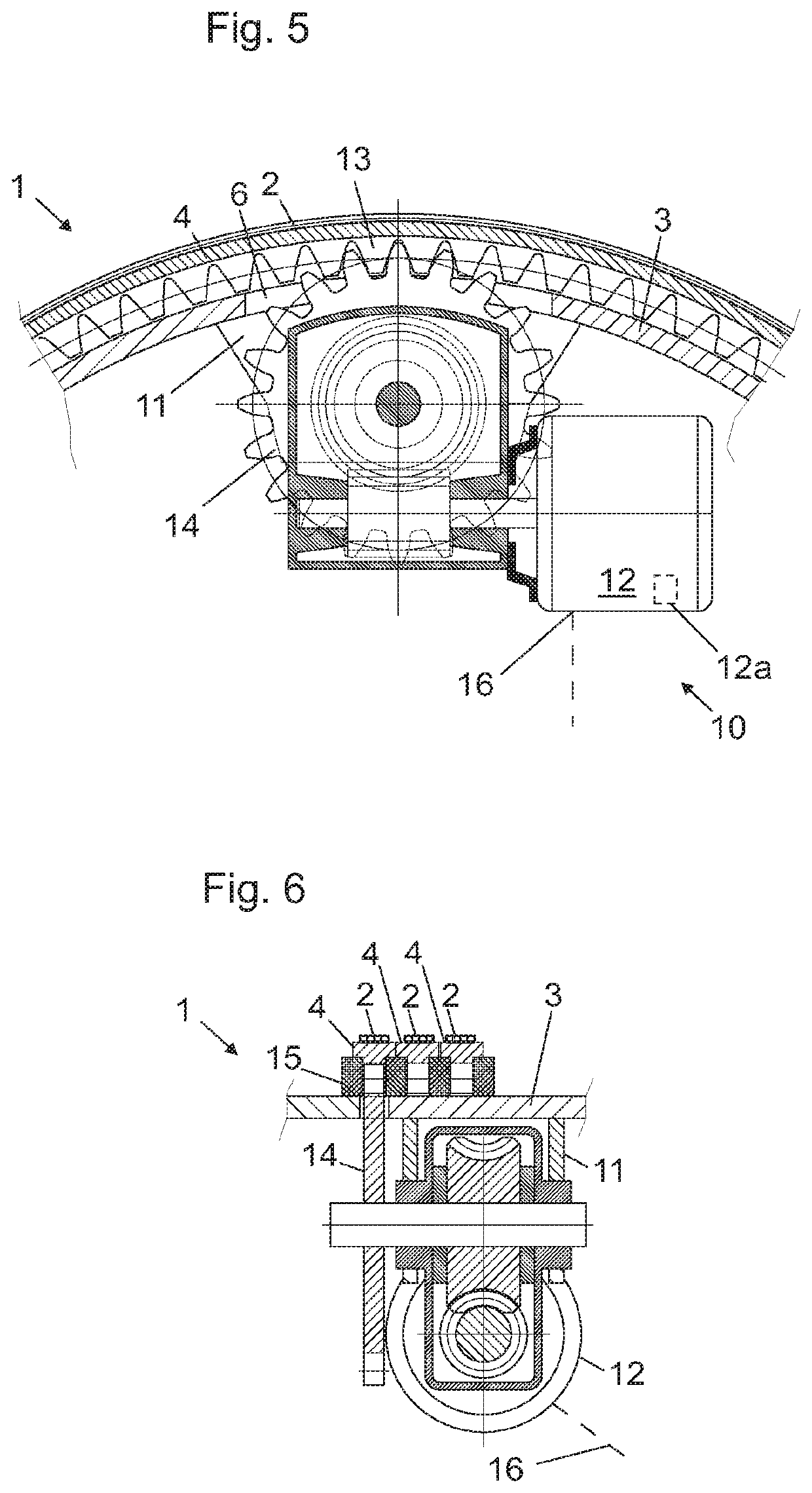
[0081]FIG. 1 illustrates a drive machinery M for an elevator according to a preferred embodiment. The drive machinery comprises a rotatable drive sheave 1 for driving plurality of ropes 2 of the elevator, the drive sheave 1 comprising a central cylinder 3, which comprises a central axis X around which the central cylinder 3 is rotatable, and a plurality of circular rim members 4 surrounding the central cylinder 3, each said circular rim member 4 comprising an outer rim surface 5 for engaging one of said ropes 2. The drive sheave 1 is arranged to exert traction force via the circular mounted circular rim members 4 on the ropes 2 passing around them.

[0082]The drive machinery M moreover comprises a motor m arranged to rotate the central cylinder 3 of the drive sheave 1. The motor m is preferably an electric motor.

[0083]FIG. 2 illustrates a schematic cross sectional view of the drive sheave 1 as seen in direction of the central axis X. Said plurality of circular rim members 4 includes r...


PUM


Abstract

The invention relates to an a drive machinery for an elevator, the drive machinery comprising a rotatable drive sheave for driving plurality of ropes of the elevator, the drive sheave comprising a central cylinder, which comprises a central axis around which the central cylinder is rotatable; plurality of circular rim members surrounding the central cylinder, each said rim member comprising an outer rim surface for engaging a rope. Said plurality of circular rim members includes one or more rotatably mounted circular rim members, each said rotatably mounted circular rim member being mounted on the central cylinder rotatably around said central axis relative to the central cylinder and relative to one or more of the other circular rim members, and in that said drive sheave moreover comprises a control means for controlling rotation of each said rotatably mounted circular rim member relative to the central cylinder and relative to one or more of the other circular rim members. The invention also relates to an elevator implementing the drive machinery.

Description

[0001]This application claims priority to European patent application no. EP18176236.0 filed on Jun. 6, 2018, the entire contents of which are incorporated herein by reference.FIELD OF THE INVENTION[0002]The invention relates to an elevator drive machinery and an elevator utilizing the drive machinery. The elevator is preferably an elevator for transporting passengers and / or goods.BACKGROUND OF THE INVENTION[0003]Elevators typically comprise a drive sheave and a roping comprising ropes connected with the elevator car and passing around the drive wheel. Via the ropes traction force can be transmitted from the drive sheave to the car. Thereby, car movement can be achieved and controlled by the drive sheave. The drive sheave can be rotatable by an electric motor, for example.[0004]The ropes driven by the drive sheave are typically connected on one side of the drive sheave with the elevator car and on the other side with a counterweight.[0005]Traction sheave elevators are prone to havin...

Claims


Application Information

Patent Timeline
Patent Type & Authority Applications(United States)
IPC IPC(8): B66B7/10B66B1/28B66B7/06B66B11/04B66B15/04
CPCB66B7/10B66B7/062B66B11/0423B66B11/043B66B15/04B66B1/28B66B17/12B66B7/06B66B15/08
Inventor HELENIUS, JUHAPELTO-HUIKKO, RAIMO
Owner KONE CORP
Why Eureka
Try Eureka