Micro yaw rate sensors

a micro-yaw rate and sensor technology, applied in the direction of acceleration measurement using interia force, instruments, devices using electric/magnetic means, etc., can solve the problems of low long-term stability and reliability material, high cost of fabrication equipment, and no mass production product success

Inactive Publication Date: 2002-06-06
LIN GANG
View PDF0 Cites 67 Cited by
  • Summary
  • Abstract
  • Description
  • Claims
  • Application Information

AI Technical Summary

Problems solved by technology

Although many micro yaw rate sensors have been invented to date, none of them has been developed into a successful mass produced commercial product yet.
With a review of the prior arts, it is apparent to those skilled in the art that most of the micro yaw rate sensors invented so far, has one or more disadvantages associated therewith, including: (a) sophisticated structure, (b) sophisticated frequency tuning and signal processing circuits, (c) expansive packaging, (d) low long term stability and reliability material, (e) high cost fabrication equipment, (f) high overall manufacturing cost.

Method used


Image

  • Micro yaw rate sensors
  • Micro yaw rate sensors
  • Micro yaw rate sensors

Examples


Embodiment Construction

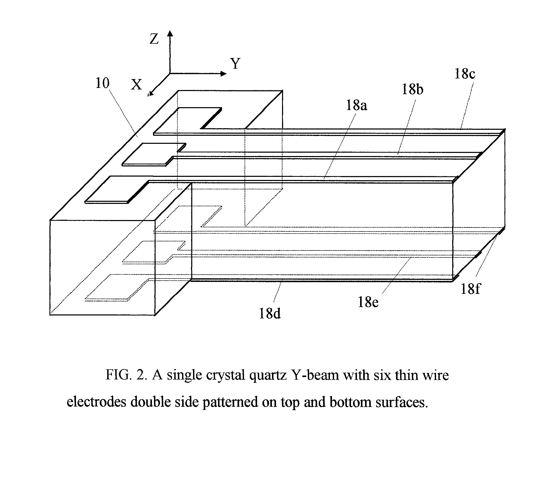
[0029] The basic structure of a yaw rate sensor made in accordance with the principle of the present invention comprises a base, a first suspension and a second suspension mounted on the base, a proof mass supported by two suspensions in such a manner that the first and second suspensions face each other across the proof mass. On the top and bottom surfaces of the first suspension there are driving electrodes, and on the second suspension the sensing electrodes.

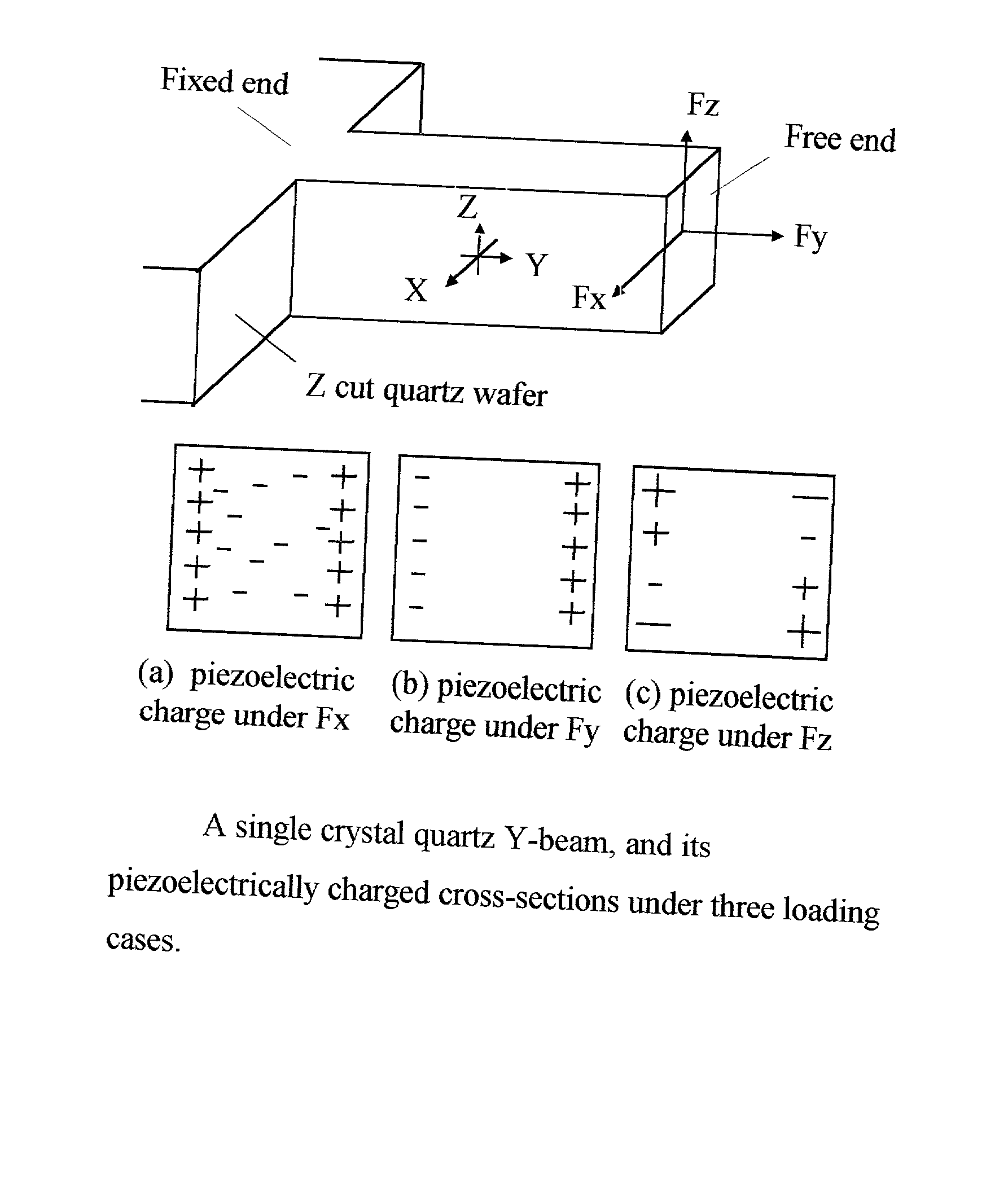
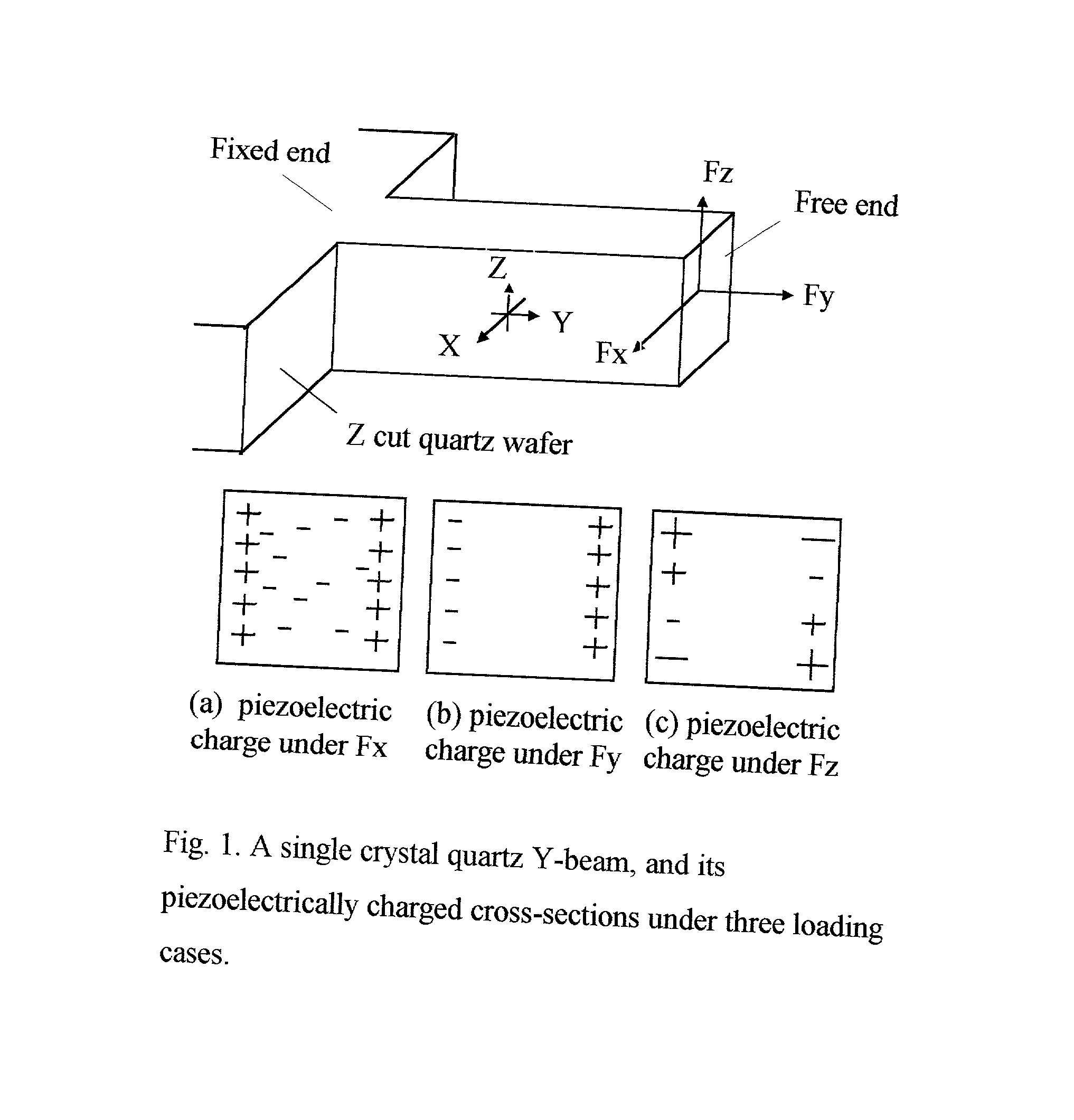
[0030] More specifically, reference is made to FIG. 5. in which is shown a first embodiment of a micro yaw rate sensor made in accordance with the principle of the present invention, and generally designated by the numeral 1. The base 10 of the sensor 1 is a Z cut monocrystalline quartz wafer. The first suspension 14 and the second suspension 16 are identical Y beams with a rectangular cross section. The proof mass and two suspensions together form a sensor resonator with sensing axis parallel to the Y axis of the crystal. Th...


PUM


Abstract

Yaw rate sensors are provided, the use of which permits quantitative measurement of yaw rate. The yaw rate sensor comprises at least a base, a first suspension and a second suspension with a proof mass supported between the two suspensions, which together form a resonator. The first suspension has a pair of thin-wire driving electrodes double side patterned on the surfaces. When a driving voltage is applied to the driving electrodes, it imposes an electric field to piezoelectrically induce a driving resonance. When the sensor is rotated around its sensing axis, the resonator will be forced to generate a sensing resonance out of the driving resonance plane to compensate the change in the linear momentum which must be conserved. The piezoelectric charge signal generated by the sensing resonance on the sensing electrodes which are double side patterned on the surfaces of the second suspension is used to detect the yaw rate. Specifically, the amplitude of the sensing resonance is in proportion to the yaw rate. The structure of the yaw rate sensors of this invention is suitable for mass production by lithographic micromachining techniques at low cost.

Description

[0001] This invention relates to micro yaw rate sensors suitable for measuring yaw rate around its sensing axis. More particularly, to micro yaw rate sensors fabricated with Z cut quartz wafer.PRIOR ART AND BACKGROUND OF THE INVENTION[0002] A micro yaw rate sensor, which is also called micro gyro, micro gyroscope or micro vibrating angular rate sensor, is a micromachined resonator with resonance sensing capability. The operation principle of the sensor follows. A linear momentum is created by an alternate driving force which excites the resonator in an oscillation. This resonance will be called driving resonance. Conservation of linear momentum implies that the vibration is restricted to the driving resonance plane defined by driving force. However, this plane is altered when the sensor is rotated around an axis parallel to the plane but perpendicular to the movement of the resonator. The original vibration, which resists this change, compensates this change by initiating a vibratio...

Claims


Application Information

Patent Timeline
Patent Type & Authority Applications(United States)
IPC IPC(8): G01C19/5642
CPCG01C19/5642
Inventor LIN, GANG
Owner LIN GANG
Why Eureka
Try Eureka