Grinding wheel

a technology of rotating wheels and workpieces, which is applied in the direction of gear teeth, grinding devices, gear teeth, etc., can solve the problems of edge re-profiles that may have to be worn down, and achieve the effects of reducing grooving on the surface of workpieces, reducing grooving on workpieces, and preferably eliminating grooving

Inactive Publication Date: 2002-06-06
3M INNOVATIVE PROPERTIES CO
View PDF0 Cites 78 Cited by
  • Summary
  • Abstract
  • Description
  • Claims
  • Application Information

AI Technical Summary

Benefits of technology

0012] Another aspect of the invention can be characterized by the layers of abrasive particles being tilted with respect to the axis of rotation of the grinding wheel to form an angle of between 0 degrees and 180 degrees, exclusive, therewith. In this way, as the grinding wheel is rotated through a 360 degree rotation, an exposed edge of a single abrasive particle layer will sweep over an axial distance wider than the width of the exposed edge of the abrasive particle layer. If the layers of abrasive particles are tilted with respect to the axis of rotation such that the width of the axial distances over which each abrasive particle layer sweeps meet or overlap, then groo...

Problems solved by technology

When a wheel having a shaped or profiled edge is used, h...

Method used


Image

  • Grinding wheel
  • Grinding wheel
  • Grinding wheel

Examples


first embodiment

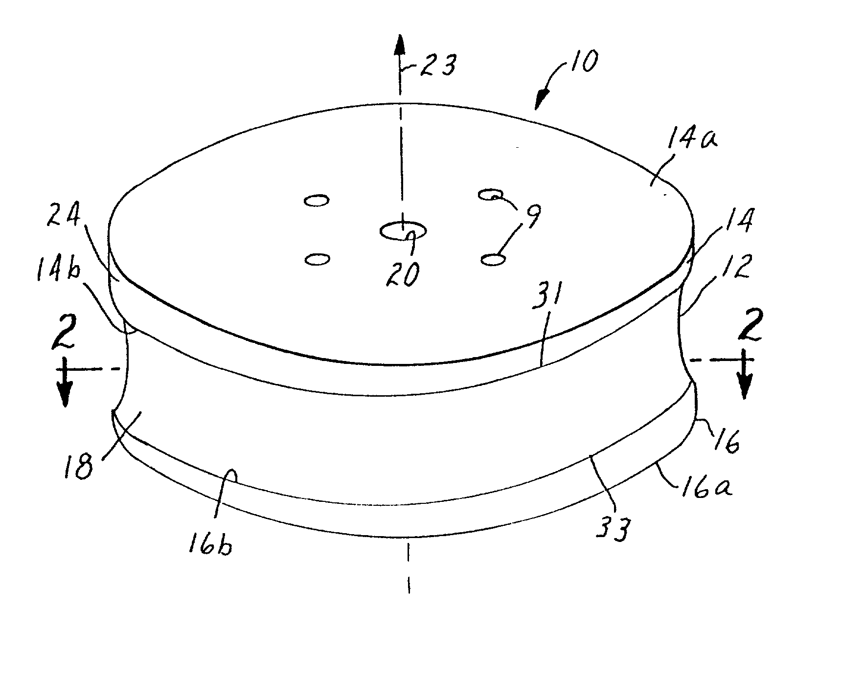
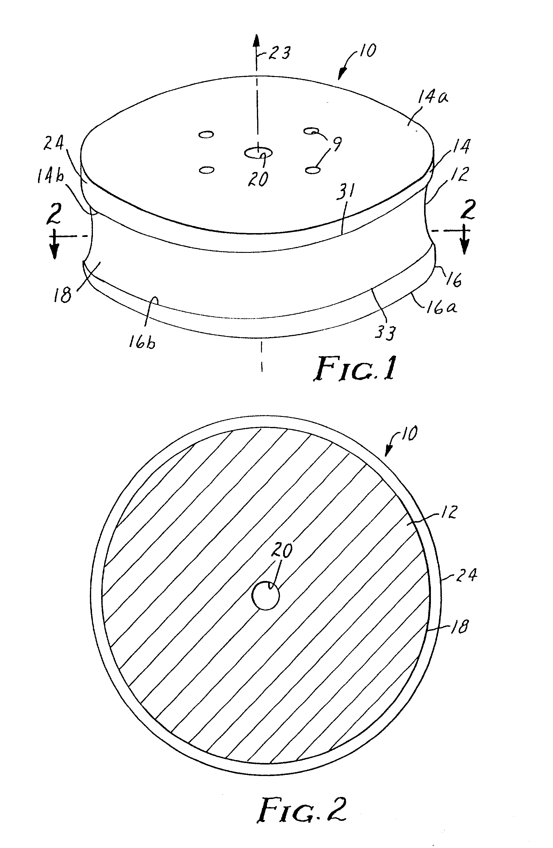
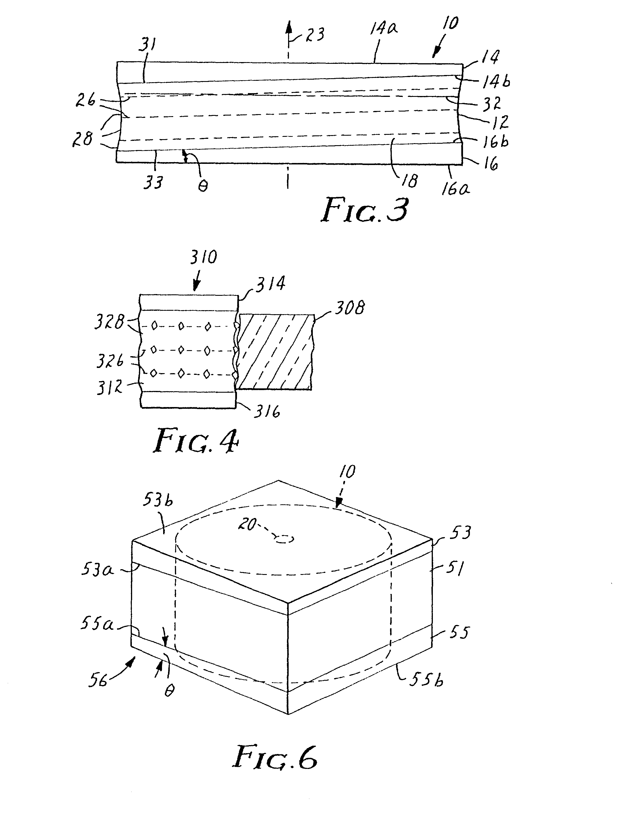
[0100] Referring now to FIG. 23 an adhesively bonded abrasive grinding wheel is shown. Grinding wheel 710 includes first support plate 714 (having inner major surface 714a and outer major surface 714b), second support plate 716 (having inner major surface 716a and outer major surface 716b), metal bond abrasive layer 712 (having first major surface 712a and second major surface 712b), first adhesive layer 715, and second adhesive layer 717. Metal bond abrasive layer 712 is a single (i.e., continuous) mass of metal bond abrasive and is interposed between first adhesive layer 715 and second adhesive layer 717. First adhesive layer 715 bonds the first major surface 712a of abrasive layer 712 to the inner major surface 714a of first support plate 714. Likewise, second adhesive layer 717 bonds the second major surface 712b of abrasive layer 712 to the inner major surface 716a of second support plate 716. Grinding wheel 710 is generally cylindrical and has bore 720 passing through a top an...

second embodiment

[0101] Referring now to FIG. 24 an adhesively bonded grinding wheel of the present invention is shown. Grinding wheel 810 includes first support plate 814 (having inner major surface 814a and outer major surface 814b), second support plate 816 (having inner major surface 816a and outer major surface 816b), metal bond abrasive layer 812, first adhesive layer 815, and second adhesive layer 817. Like wheel 710, wheel 810 via bore 820 and optional mounting holes 809 can be mounted on a rotatable shaft (not shown) and rotated about axis of rotation 823. Metal bond abrasive layer 812 is made up of a plurality of discrete metal bond abrasive segments 813 which are circumferentially spaced about the perimeter of wheel 810. The abrasive segments 813 each have first major surface 813a and second major surface 813b. The metal bond abrasive segments 813 are interposed between first adhesive layer 815 and second adhesive layer 817. First adhesive layer 815 bonds the first major surfaces 813a of ...

third embodiment

[0102] Referring now to FIGS. 25a and 25b, an adhesively bonded grinding wheel of the present invention is shown. Grinding wheel 910 includes first support plate 914 (having inner major surface 914a and outer major surface 914b), second support plate 916 (having inner major surface 916a and outer major surface 916b), abrasive layer 912, first adhesive layer 915, and second adhesive layer 917. Like wheel 710, wheel 910 via bore 920 and optional mounting holes 909 can be mounted on a rotatable shaft (not shown) and rotated about axis of rotation 923. As shown in FIG. 25b, first support plate 914 includes axially extending surface 930. Second support plate 916 has inner circular opening 922 which mates with first support plate 914 over axially extending surface 930. Abrasive layer 912 is made up of a plurality of discrete metal bond abrasive segments 913 which are circumferentially spaced about the perimeter of grinding wheel 910. The abrasive segments 913 each have a first major surfa...


PUM


Abstract

A cylindrical, abrasive grinding wheel having a cylindrical abrasive region with an abrasive surface at an outer circular band thereof. The abrasive region includes layers of abrasive particles. The layers of abrasive particles can be tilted with respect to an axis of rotation of the grinding wheel or they can such that grooving in the grinding wheel and a workpiece ground by the grinding wheel can be reduced. Alternatively, the abrasive region can be formed from a plurality of abrasive segments each having layers of abrasive particles. The layers of abrasive particles can be staggered in the direction of the axis of rotation from one segment to another. This can also reduce grooving in the grinding wheel and workpieces.

Description

[0001] This application is a continuation-in-part of pending prior application Ser. No. 09 / 019,657, filed on Feb. 6, 1998.TECHNICAL FIELD[0002] The present invention relates generally to abrasive or superabrasive tools. In particular, the present invention relates to a rotatable grinding wheel having an abrasive or superabrasive surface.BACKGROUND OF THE INVENTION[0003] Certain types of workpieces (plastic and glass lenses, stone, concrete, and ceramic, for example) can be advantageously shaped using grinding tools, such as a wheel or disc, which have an abrasive work surface, particularly a superabrasive work surface, a superabrasive surface also being an abrasive surface but having a higher abrasivity. The work surface of the grinding tool can be made up of an abrasive band around the outer circumference of the wheel or disk. The work surface usually includes particles of super hard or abrasive material, such as diamond, cubic boron nitride, or boron suboxide surrounded by a bond ...

Claims


Application Information

Patent Timeline
IPC IPC(8): B24D3/06B24D5/02B24D5/06B24D5/10B24D5/16B24D18/00
CPCB24D3/06B24D5/02B24D18/00B24D5/10B24D5/16B24D5/066B24D5/06
Inventor CESENA, ROBERT T.TSELESIN, NAUM N.PALMGREN, GARY M.PRESTON, JAY B.
Owner 3M INNOVATIVE PROPERTIES CO
Why Eureka
Try Eureka