
Robot, servo circuit, actuator, robot control method, and actuator driving method

a technology of servo circuits and actuators, applied in adaptive control, program control, instruments, etc., can solve the problems of increasing limiting the operation speed of the entire robot, so as to achieve the effect of small size and acceleration of the operation speed

Inactive Publication Date: 2002-06-27
SONY CORP
View PDF0 Cites 42 Cited by
  • Summary
  • Abstract
  • Description
  • Claims
  • Application Information

AI Technical Summary

Benefits of technology

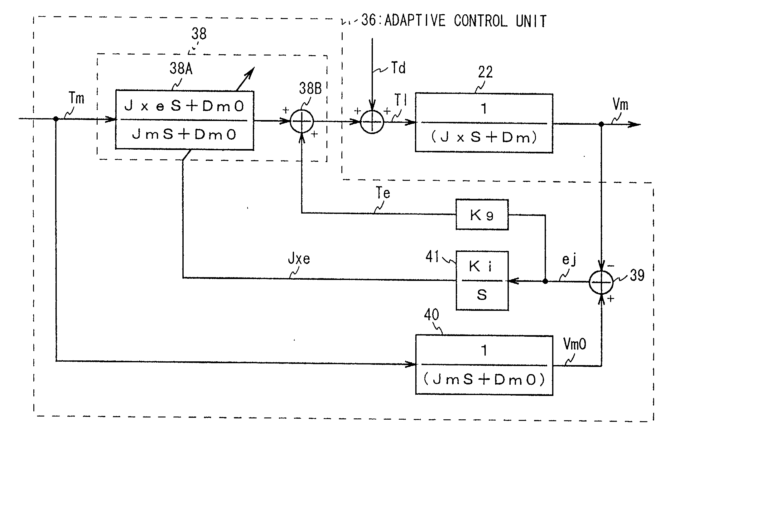
[0021] As a result, by correcting a control value to be input to an actuator driving system and / or a model driving system so that responses from an actuator and a model coincide with each other, the robot can detect a moment of inertia of the actuator in real-time based on a result of the correction with a moment of inertia set for the model as a reference. Thereby, by correcting the control value based on the detection result, it is possible to cope with an unpredictable disturbance without providing a special sensor.
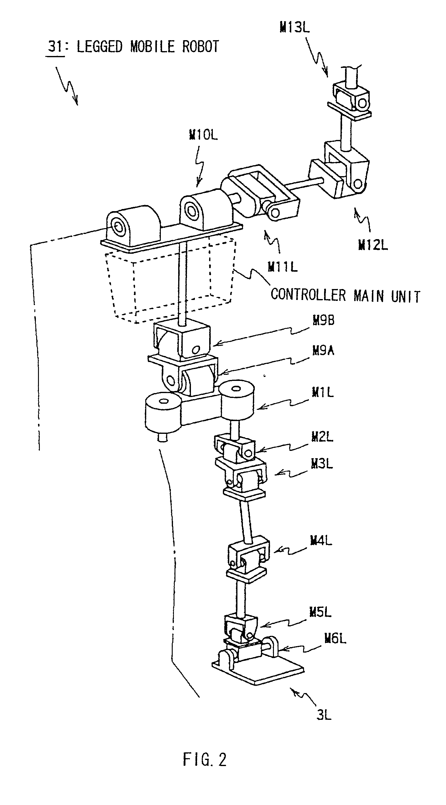
[0045] In the legged mobile robot 31, the actuator M6L is joined to the actuator M5L by a joiner, and the rotational axis of the actuator M6L is positioned to be perpendicular to the rotational axis of the actuator M6L. This enable the legged mobile robot 31 to rotate the sole right and left by driving the actuator M5L, as denoted by reference numeral .theta.2. Accordingly, the legged mobile robot 31 drives the actuators M5L and M6L in association with other actuators and inclines the sole back and forth, and right and left, in accordance with a rough floor, thereby enabling walking even on a rough floor.
[0072] In other words, in the case of walking on the flat floor, when the sole touches the ground, as shown in FIG. 6, the load moment of inertia, which has been a small value, increases, and the increase is detected by the optimization regulator 34. In this case where walking on the flat floor is performed, when such increase in the load moment of inertia is set beforehand so as to be adapted for the control object value for each actuator, in the egged mobile robot 31, control of each actuator performed until the sole touches the ground, and control performed after the sole touches the ground change in accordance with prior settings, whereby accidents such as falling is prevented, enabling stable walking.
[0073] Differently therefrom, for example, while similar control object values are being output from the control command generator 11, when the floor on which the legged mobile robot 31 moves inclines, or the floor is rough, the floor inclination or the roughness cause each motor M to have a change in the moment of inertia and the load caused by the disturbance, and in accordance with the change, the optimization regulator 34 generates the amount of operation, which corrects the control object value. Accordingly, control object values for motors, etc., constituting the ankle joint and the knee joint are corrected so that a region touching the floor is inclined in accordance with, for example, the roughness of the floor, whereby unstable movements, which are caused by a disturbance which is difficult to predict, are prevented.
[0075] In other words, as shown in, for example, FIG. 7, in the case where walking on an upward floor is performed, compared with the case where walking on the flat floor is performed, the sole touches the ground earlier, and the load moment of inertia that has been a small value increases. In this case, the optimization regulator 34 corrects the control value in accordance with the sole inclination A 0 by detecting the increase in the load moment of inertia, corrects the center of gravity so that the position of the center of gravity copes with the disturbance, in other words, so that a condition is established which is similar to the case where the sole touches the ground when walking on the flat floor is performed, and switches control of the sole in back and forth directions, whereby accidents such as falling is prevented, enabling stable walking.
[0076] In addition, in the legged mobile robot 31, the optimization regulator 34 generates, instead of each sensor provided for each region, the amount of operation, based on the moment of inertia sent from each servo circuit, and on the load caused by the disturbance. This enables the legged mobile robot 31 to omit a sensor provided for each region as provided in the conventional legged mobile robot, and the entire construction can be small-sized and simplified by the omission, and the operation speed can be accelerated.

Problems solved by technology

In the case that a control object in each servo circuit is corrected based on a detection result obtained by an attitude sensor, etc., as described above, a force sensor, a contact sensor, etc., must be provided for each component constituting legs, and the provision for each component causes a problem in that the entire structure is complicated and enlarged.
The enlargement and increase in weight causes a further problem in that increasing the operation speed of the entire robot is difficult.
A force sensor for this type has small rigidity, which makes it difficult to accelerate the operation speed of the entire robot.
Moreover, when it becomes difficult to cope with an unpredictable change in a load, the movement is unstable due to the load change depending on the level of difficulty.
In walking, the load moment of inertia repeatedly reaches its maximum and minimum, and the attitude of the entirety causes a complicated change in the load moment of inertia of each motor.
Differently from the above-described case, prediction of the roughness of the floor is difficult.

Method used


Image

  • Robot, servo circuit, actuator, robot control method, and actuator driving method
  • Robot, servo circuit, actuator, robot control method, and actuator driving method
  • Robot, servo circuit, actuator, robot control method, and actuator driving method

Examples


Embodiment Construction

[0078] According to the above-described construction, by driving the motor M based on the control value Tm, the response Vm from the motor M to be driven and the response Vm0 from the model 40 of the motor M, the moment of inertia of the motor M can be detected, and therefore, the moment of inertia of a thing to be driven can be detected in real-time without providing any special sensor.

[0079] In other words, in a servo system that controls the angle of a joint, by correcting the control value Tm so that the response Vm from the motor M to be driven is set to equal to the response Vm0 form the model 40 of the motor M, and also by detecting, based on a result of the correction of the control value Tm, at least the moment of inertia of the motor M, an object to be driven can be detected in real-time without providing any special sensor.

[0080] This enables the robot to use a simplified structure to prevent unstable operations caused by a disturbance, and to have an accelerated moving s...


PUM


Abstract

Based on a control object, a result of the detection of driving of an actuator and a response from a standard mathematical model of the actuator, the actuator is controlled, or in a servo system that controls the angle of a joint, etc., the control value is corrected so that the response from the thing to be driven and the response from the model of the thing to be driven are set to coincide with each other, and also based on a result of the correction of the control value, at least the moment of inertia of the thing to be driven is detected. Thereby, the moment of inertia of the driver and the like can be detected in real-time without providing a special sensor.

Description

[0001] The present invention relates to robots, servo circuits, actuators, robot control methods, and actuator driving methods, and can be applied to, for example, two- or four-legged mobile robots. The present invention allows the moment of inertia of a driver and the like to be detected in real-time without providing special sensors, by controlling an actuator based on a control object, a result of detecting the movement of the actuator and a response from a standard mathematical model of the actuator; and also in a servo system or the like, by correcting a control value so that responses from an object to be driven and a model of the object to be driven are identical and moreover, by detecting at least the moment of inertia of the object to be driven based on a result of the control value correction.[0002] Hitherto, a legged mobile robot that uses two legs to move can be moved with the two legs by controlling a plurality of joint actuators provided in the legs. FIG. 8 is a skelet...

Claims


Application Information

Patent Timeline
Patent Type & Authority Applications(United States)
IPC IPC(8): B25J9/16B25J9/18B62D57/032
CPCB25J9/1638G05B2219/41381G05B2219/40358B62D57/032
Inventor ISHII, SHINJIKUROKI, YOSHIHIRO
Owner SONY CORP
Learn More