Output protected energiser

Inactive Publication Date: 2002-06-27
TRU TEST
View PDF0 Cites 39 Cited by
  • Summary
  • Abstract
  • Description
  • Claims
  • Application Information

AI Technical Summary

Problems solved by technology

However a disadvantage is that if at any time the energiser is operating into a heavy load (say 100 ohms) and has reached a high level of stored energy to have good performance into this load and then the load suddenly reduces the energiser hav

Method used


Image

  • Output protected energiser
  • Output protected energiser
  • Output protected energiser

Examples


Embodiment Construction

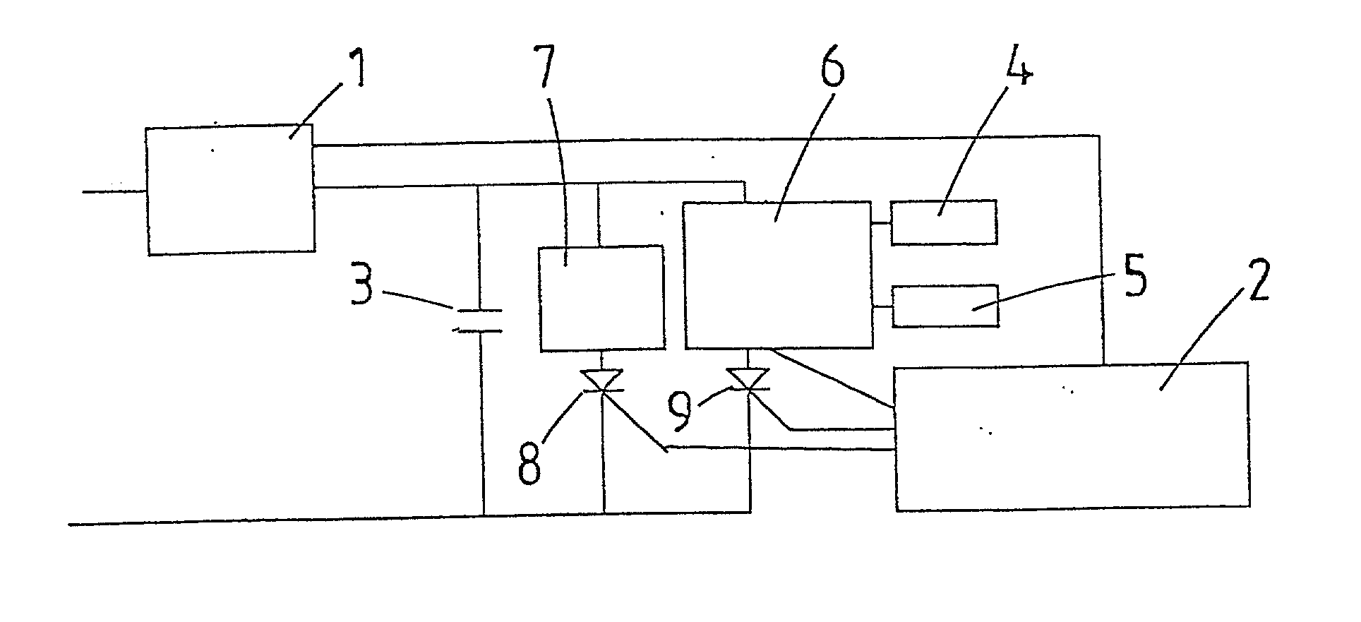
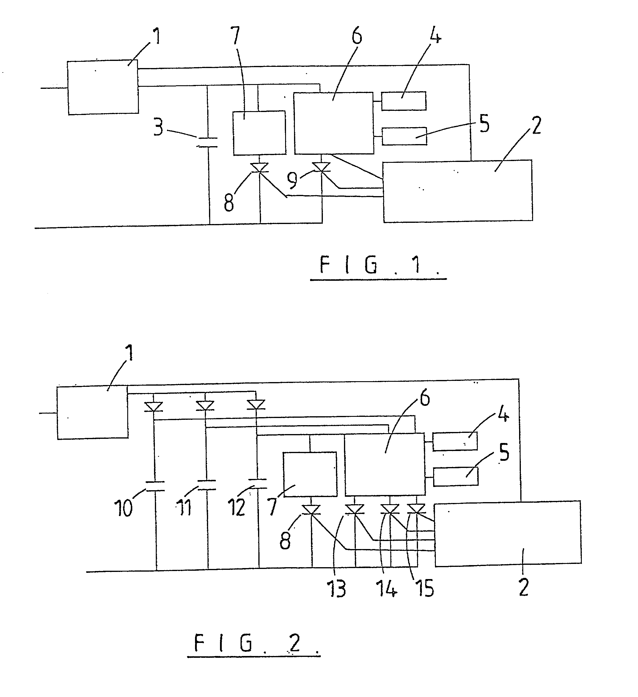
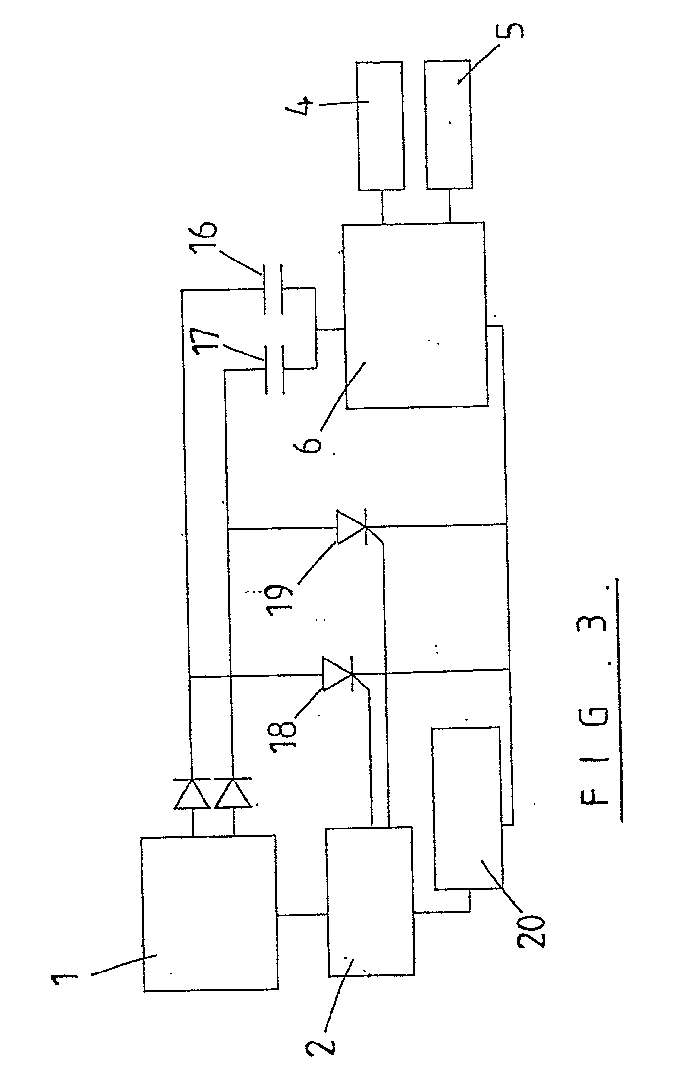
[0018] Ideally the voltage and / or energy level sent along an electric fence line in each pulse changes as the sensed load on the fence line changes so that the most effective shock is given to any animal in contact with the fence line. This is usually achieved by sensing the load on the fence line and changing the voltage and / or energy of the next pulse in proportion with the sensed load. As the load increases, for example as grass and weed growth comes into contact with the fence line, the voltage and / or energy of the output pulses is increased. However there is a one pulse delay between sensing the load and sending out a pulse with voltage and / or energy level appropriate to the load. This does not create problems when the load is increasing as the animals in contact with the fence line will be shocked by a pulse with voltage and / or energy lower than the maximum allowed by safety standards, but if the load decreases during the period between pulses the next pulse can be at too high...


PUM


Abstract

An electric fence energiser for coupling to an electric fence line. The energiser includes a sensor to sense the load on the fence line, at least one storage capacitor, and a charge circuit to charge the storage capacitor(s). A control circuit provides an output pulse with energy appropriate to the sensed load and determines whether the current pulse will exceed a predetermined limit adjustment and adjust the output pulse to send out an output pulse with voltage and/or energy below the predetermined limit if the current pulse will exceed said limit.

Description

[0001] The present invention relates to an electric fence energiser arranged to produce output pulses that fall within required safety standards during rapid decreases in the fence line load.BACKGROUND TO THE INVENTION[0002] Energisers that control the level of the energiser output pulses proportional to the load on the fence line are currently available. Typically such energisers sense the load on the fence line during one pulse and adjust the voltage of the next output pulse dependent on the sense load. However these energisers whilst complying with output safety standards are capable of delivering pulses outside the limits given in safety standards if rapid decreases in load occur.[0003] Output controlled energisers operate by checking the voltage of the last pulse. If this is lower than the designed performance for the sensed load the energiser control system increases the voltage of the next pulse, (usually by increasing the level of energy stored on the capacitor(s) of the ene...

Claims


Application Information

Patent Timeline
IPC IPC(8): H05C1/04
CPCH05C1/04
Inventor REEVES, JACK HARTSTONE
Owner TRU TEST
Why Eureka
Try Eureka