Apparatus and method for simulating the receiving characteristic of radio waves

a radio wave and receiver technology, applied in the field of apparatus and method for simulating the receiving characteristic of radio waves, can solve the problem of taking an enormous time to calculate all

Inactive Publication Date: 2002-06-27
FUJITSU LTD
View PDF3 Cites 7 Cited by
  • Summary
  • Abstract
  • Description
  • Claims
  • Application Information

AI Technical Summary

Problems solved by technology

However, the conventional calculation method described above has the following problems.
Therefore, if the number of system elements increases, it takes an enormous time to calculate all elements of the mutual impedance Z.sub.ij composing mutual impedance matrix[Z.sub.ij].

Method used


Image

  • Apparatus and method for simulating the receiving characteristic of radio waves
  • Apparatus and method for simulating the receiving characteristic of radio waves
  • Apparatus and method for simulating the receiving characteristic of radio waves

Examples


Embodiment Construction

[0031] The detailed preferred embodiments are described below with reference to the drawings.

[0032] FIG. 2A shows the basic configuration of the simulation apparatus of the present invention. The simulation apparatus shown in FIG. 2A comprises current calculation devices 21 and 22, a current storage device 23 and an output device 24. The apparatus simulates the receiving characteristic of an object that receives radio waves transmitted from a wave source.

[0033] The current calculation device 21 calculates the current values of the wave source using the simultaneous equations of the wave source, which have currents that flow through respective elements as unknowns when the wave source is divided into a plurality of elements. The current storage device 23 stores the current values of the wave source. The current calculation device 22 calculates the current values of the object using the simultaneous equations of the object, which have currents that flow through respective elements and...


PUM


Abstract

In Moment method, by regarding the current values of a wave source to be constants, the simultaneous equations of the wave source and the simultaneous equations of a receiving object can be separated and the current values of the wave source and the current values of the object can be separately calculated. Even if the positional relationship between the wave source and object changes, the mutual impedance between the elements of the object does not change. Therefore, there is no need to calculate the coefficient matrix of the simultaneous equations of the object again.

Description

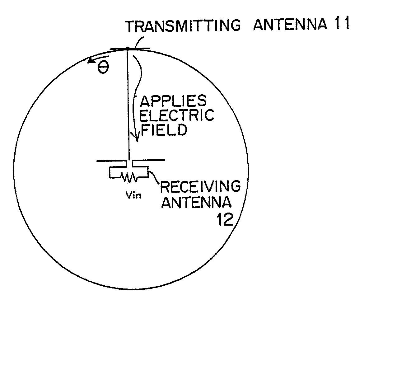
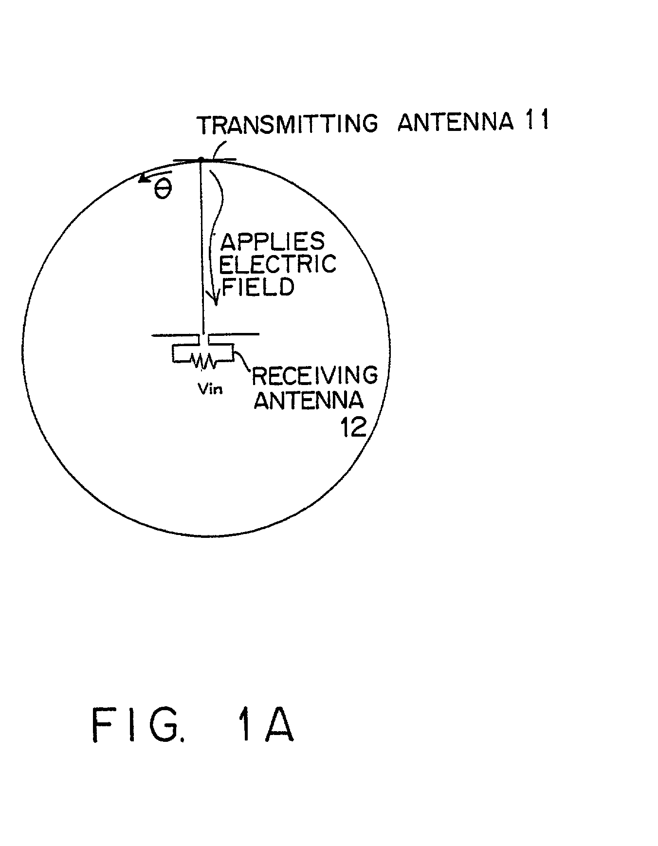
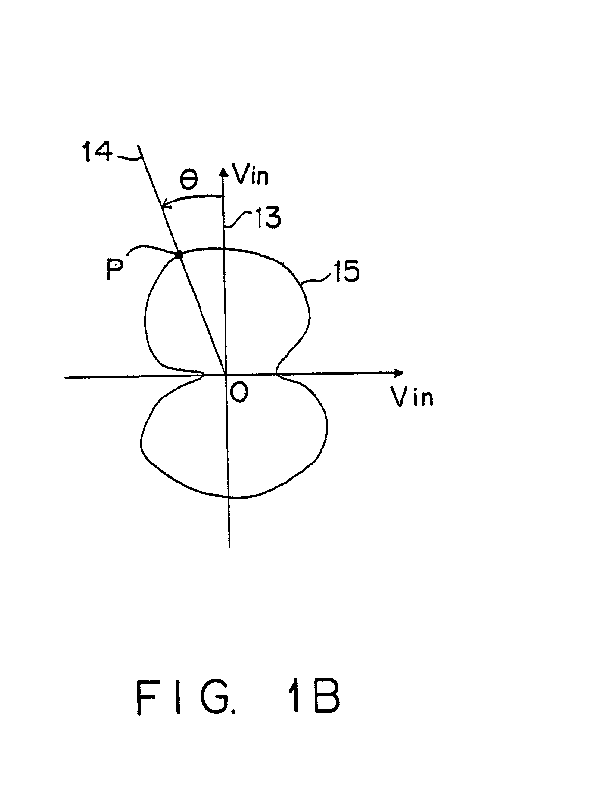
[0001] 1. Field of the Invention[0002] The present invention relates to an apparatus for simulating the receiving characteristic of an object that receives radio waves in the analysis of radio waves transmitted from a radio wave generation source and a method thereof.[0003] 2. Description of the Related Art[0004] Receiving sensitivity based on the directivity characteristic of an antenna is the major factor of a product that receives radio waves from outside, such as a cellular phone, a car antenna, etc. These products are assumed to be called "equipment under test (EUT) ". Software programs for virtually modeling and calculating the directivity characteristic against radio waves from outside of an EUT are conventionally used.[0005] FIG. 1A shows the relationship between a transmitting antenna, which is a radio wave generation source (wave source) and a receiving antenna included in an EUT, in such a model. In FIG. 1A, the directivity characteristic of a receiving antenna 12 can be ...

Claims


Application Information

Patent Timeline
Patent Type & Authority Applications(United States)
IPC IPC(8): G06F17/50
CPCG06F2217/84G06F17/5009G06F2119/12G06F30/20
Inventor YAMAGUCHI, SHINYANAGASE, KENJIOHTSU, SHINICHIMUKAI, MAKOTO
Owner FUJITSU LTD
Why Eureka
Try Eureka