Mounting bracket

a mounting bracket and bracket technology, applied in the field of mounting brackets and devices, can solve the problems of deteriorating the signal quality, affecting the aesthetic appearance of the reflector, and the mounting apparatus cannot accommodate relatively fine adjustments to the antenna, so as to achieve the effect of easy adjustmen

Inactive Publication Date: 2002-07-04
BELLSOUTH INTPROP COR
View PDF0 Cites 95 Cited by
  • Summary
  • Abstract
  • Description
  • Claims
  • Application Information

AI Technical Summary

Benefits of technology

0013] It is a feature of the present invention to provide a mounting bracket that can be attached to a supporting structure, such as a building, tree, vertically extending pole or mast and that can adjustably support an object in desired orientations.
0014] It is another feature of the present invention to provide a mounting bracket that pivotally supports an object about a first axis and that can be readily adjusted to pivot the object about the first axis in a precise and controlled manner and locked in position after the adjustments have been completed.

Problems solved by technology

It will be appreciated that the process of tightening the locking bolts can actually cause the antenna to move out of its optimum position which can deteriorate the quality of the signal or, in extreme situations, require the installer to re-loosen the bolts and begin the alignment process over again.
Furthermore, such mounting apparatuses cannot accommodate relatively fine adjustments to the antenna.
In addition, because such crude bracket arrangements are attached directly to the rear of the reflector, they can detract from the reflector's aesthetic appearance.

Method used


Image

  • Mounting bracket
  • Mounting bracket
  • Mounting bracket

Examples


Embodiment Construction

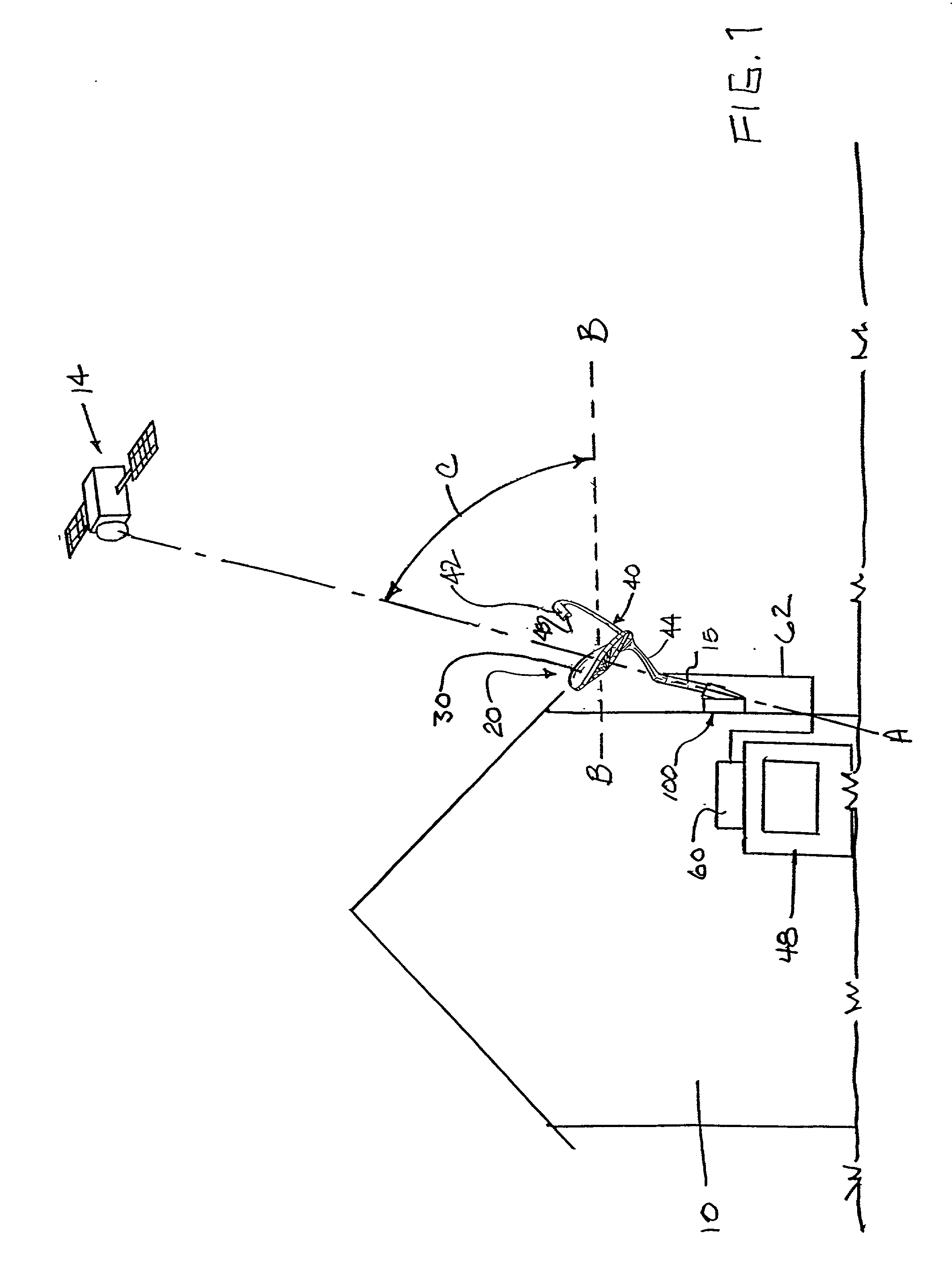
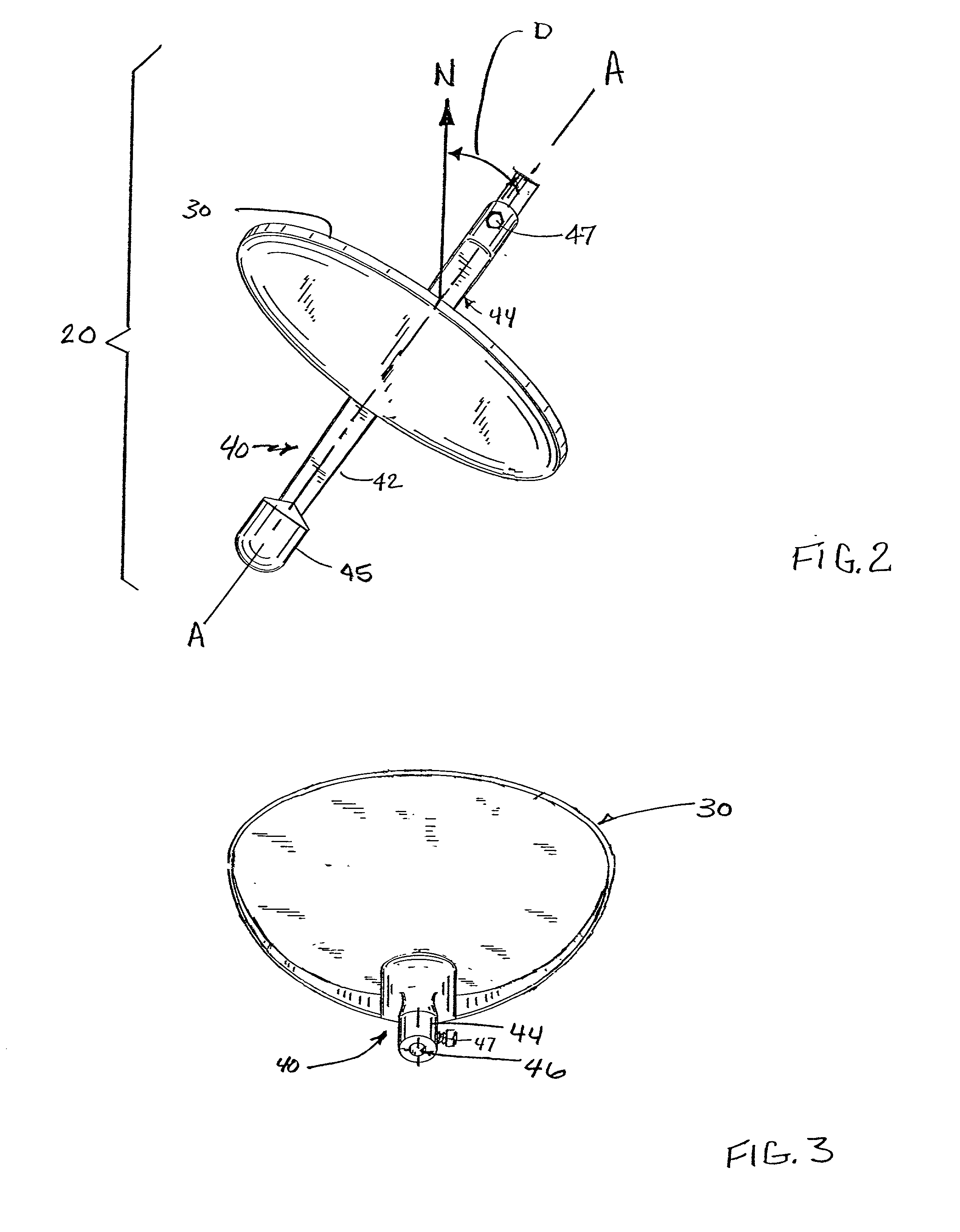
[0046] Referring now to the drawings for the purposes of illustrating embodiments of the invention only and not for the purposes of limiting the same, FIG. 1 illustrates an antenna 20 that is attached to the wall of a residence or other building 10 by a mounting bracket 100 of the present invention. The antenna 20 is oriented to receive audio, video and data signals from a satellite 14 in geosynchronous orbit around the earth. The antenna 20 includes parabolic reflector 30 and an arm assembly 40 that includes a forwardly extending portion 42 that supports a feed / LNBF assembly 45 for collecting focused signals from the reflector 30. Such feed / LNBF assemblies are known in the art and, therefore, the manufacture and operation of feed / LNBF assembly 45 will not be discussed herein.

[0047] The antenna 20 is attached to a satellite broadcast receiver ("set top box") 60 by coaxial cable 62. The set top box 60 is attached to a television monitor 48. Such set top boxes are known in the art and...


PUM


Abstract

A mounting bracket for adjustably supporting an object about one or more axes. The bracket may include a support member that is pivotally attached to a mounting member such that the support member may be selectively pivoted about a first pivot axis relative to the mounting member and thereafter releasably locked in that position. Adjustment components may be provided to facilitate controlled pivotal travel of the support member about the first pivot axis and which non-movably retains the support member in a desired position as the locking members are locked. The bracket may further comprise an antenna mast support member that is pivotally attached to the support member for selective pivotal travel about a second pivot axis relative to the support member and thereafter releasably locked in position. Additional adjustment components may be provided to facilitate the controlled pivotal travel of the antenna mast support member about the second pivot axis and which non-movably retains the antenna mast support member in a desired position as it is locked in that position.

Description

[0001] 1. Field of the Invention[0002] The subject invention relates to mounting brackets and devices and, more particularly, to brackets for adjustably supporting objects including antennas and the like.[0003] 2. Description of the Invention Background[0004] The advent of the television can be traced as far back to the end of the nineteenth century and beginning of the twentieth century. However, it wasn't until 1923 and 1924, when Vladimir Kosma Zworkykin invented the iconoscope, a device that permitted pictures to be electronically broken down into hundreds of thousands of components for transmission, and the kinescope, a television signal receiver, did the concept of television become a reality. Zworkykin continued to improve those early inventions and television was reportedly first showcased to the world at the 1939 World's Fair in New York, where regular broadcasting began.[0005] Over the years, many improvements to televisions and devices and methods for transmitting and rec...

Claims


Application Information

Patent Timeline
Patent Type & Authority Applications(United States)
IPC IPC(8): F16M11/12H01Q1/12
CPCF16M11/10F16M11/12F16M11/2028F16M13/02F16M2200/022H01Q1/1221H01Q1/125
Inventor WEAVER, TIMOTHY H.
Owner BELLSOUTH INTPROP COR
Why Eureka
Try Eureka