Pilot-type channel valves providing counter-flow prevention

a technology of channel valves and valves, which is applied in the direction of functional valve types, water supply installation, operating means/releasing devices of valves, etc., can solve the problems of inability to prevent counter-flow, increase the size of channel valves, and the counter-flow prevention valve cannot recover from freezing

Inactive Publication Date: 2002-07-11
AISAN IND CO LTD
View PDF0 Cites 16 Cited by
  • Summary
  • Abstract
  • Description
  • Claims
  • Application Information

AI Technical Summary

Benefits of technology

[0007] In the pilot-type channel valve according to the present invention, a counter-flow prevention valve is disposed within the body of the pilot-type channel valve. When a counter-flow prevention valve is disposed within the body of the pilot-type channel valve, while electrical power is applied to the solenoid coil and the pilot-type channel valve is open, or while a high-pressure working fluid is introduced and the pilot-type channel valve is open, i.e., while a gas is flowing through the counter-flow prevention valve while undergoing adiabatic expansion, the heat generated by the application of the electrical power to the solenoid coil or the heat generated by the introduction of the working fluid is conducted through the body and is efficiently transferred to the counter-flow prevention valve. Therefore, even if the gas flowing in the channel contains water vapor and even when this gas cools due to significant expansion, the water vapor can be prevented from freezing within the counter-flow prevention valve. Moreover, even if freezing should occur for some reason, the heat from the solenoid coil or the heat generated by the adiabatic compression of the working fluid is conducted through the body and is efficiently transferred to the counter-flow prevention valve, thereby quickly thawing the frozen area. Furthermore, because the counter-flow prevention valve is disposed within the body of the pilot-type channel valve, the pipe volume between the pilot-type channel valve and the counter-flow prevention valve is small. Consequently, the pressure within the pipe rises quickly, thereby opening the counter-flow prevention valve without delay. Therefore, in order to provide a structure for opening and closing a channel while preventing counter-flow, the valve of the present invention can be used to achieve desirable characteristics, i.e., the counter-flow prevention valve is resistant to freezing and the valve itself has an excellent valve-opening response, particularly for a pipe that supplies hydrogen to fuel cells, which has been gaining much attention in recent years, while enjoying the advantage of a pilot-type channel valve, which is the ability to be driven by a small amount of power. A pilot-type channel valve providing counter-flow prevention according to the present invention is extremely useful for a hydrogen-supply pipe, because water vapor is mixed within such a pipe and because hydrogen passes through the pipe while undergoing volume changes. Note that in the case of the present invention, its advantages, i.e., the ability to be driven by a small amount of power, the resistance to freezing, and the excellent valve-opening response, can be enjoyed even if the counter-flow prevention valve is inserted on the upstream side of a pilot-type channel valve.

Problems solved by technology

However, a pilot-type channel valve is characterized in that it has an inability to prevent counter-flow.
However, the first means, i.e., a channel valve that is closed by means of a large spring force and is opened by applying a large amount of power in order to open and close the channel while preventing counter-flow, requires a large amount of power for opening and closing the channel, thereby increasing the size of the channel valve.
However, this method still faces a problem in that the counter-flow prevention valve cannot recover from freezing once it becomes inoperable due to freezing.
When the fluid that flows through the channel is a gas, the gas flows through the channel while being compressed or expanded, resulting in gas temperature fluctuations.
If the gas contains water vapor, this water vapor may freeze within the counter-flow prevention valve.
In this case, if a counter-flow phenomenon occurs after the pilot-type channel valve has closed, the counter-flow prevention valve, which is intended to prevent a counter-flow, becomes frozen in the open position and cannot prevent counter-flow.
Also, it is not possible to heat the counter-flow prevention valve to prevent it from freezing when the gas, which has been cooled by undergoing adiabatic expansion, is passing through this counter-flow prevention valve; as a result, the valve tends to freeze.
Moreover, the method of inserting a counter-flow prevention valve within the pipe downstream from a pilot-type channel valve also has a problem of poor valve-opening response.
In the method of inserting a counter-flow prevention valve in the downstream pipe, it takes time for the pressure to rise, because the capacity of the pipe between the pilot-type channel valve and the counter-flow prevention valve is large.

Method used


Image

  • Pilot-type channel valves providing counter-flow prevention
  • Pilot-type channel valves providing counter-flow prevention
  • Pilot-type channel valves providing counter-flow prevention

Examples


Embodiment Construction

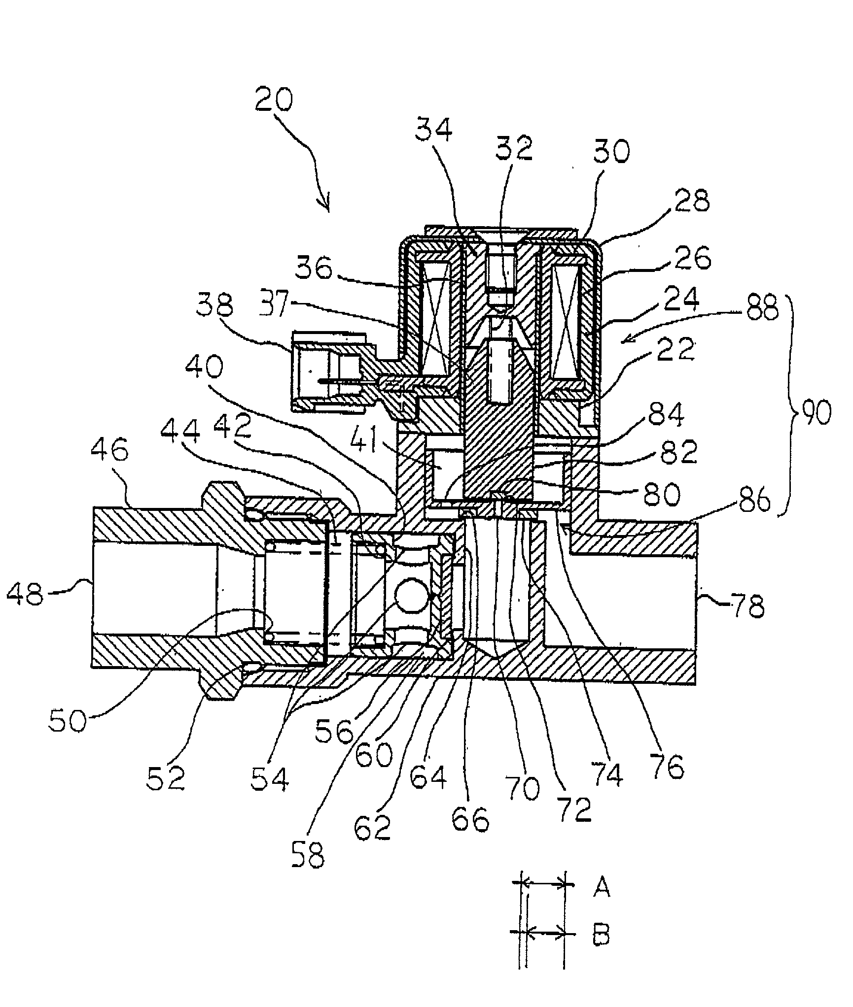
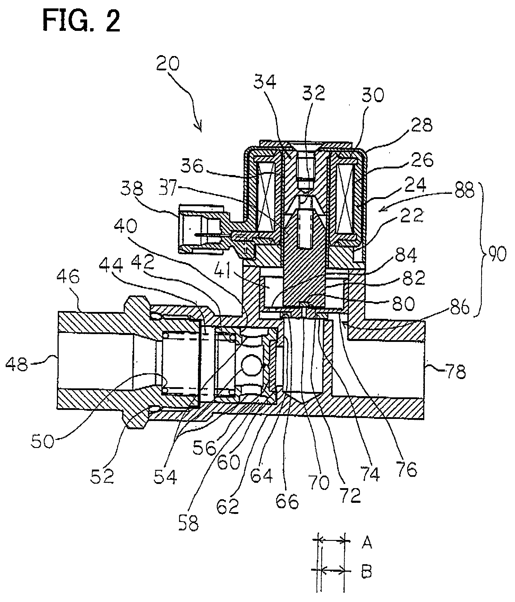
[0011] Preferred embodiments of the pilot-type channel valve providing counter-flow prevention according to the present invention are explained below. FIG. 2 shows a cross-sectional drawing of a pilot-type channel valve 20 providing counter-flow prevention. Pilot-type channel valve 20 providing counter-flow prevention is constructed by disposing a pilot-type channel valve 90 and a counter-flow prevention valve 40 within a body 62. Pilot-type channel valve 90 and counter-flow prevention valve 40 are connected in series and are disposed in close proximity to each other within body 62. Body 62 is formed from a material possessing a large thermal conductivity, such as aluminum.

[0012] Next, the structure will be explained in detail. Pilot-type channel valve 90 consists of a movable area 86 and an electromagnetic force generation area 88. Movable area 86 primarily consists of a main valve 76 and a pilot valve 82. Main valve 76 is cylindrical in shape and has a bottom, and has an outside d...


PUM


Abstract

A counter-flow prevention valve is disposed within a body of a pilot-type channel valve. While electrical power is applied to a solenoid coil and the pilot-type channel valve is opened, i.e., while a gas is flowing through the counter-flow prevention valve and the gas is expanding, heat generated by the application of electrical power to the solenoid coil is conducted via the body and is effectively transferred to the counter-flow prevention valve. Therefore, even if the gas contains water vapor and even if this gas is cooled due to significant expansion, the water vapor can be prevented from freezing within the counter-flow prevention valve. Moreover, the volume of the pipe between the pilot-type channel valve and the counter-flow prevention valve is small, thereby resulting in a fast rise in pressure within the pipe and a quick opening of the counter-flow prevention valve, which provides an excellent valve-opening response.

Description

[0001] The present invention relates to techniques for preventing counter-flow in a pilot-type channel valve. More particularly, an objective of the present invention is to realize a pilot-type channel valve providing counter-flow prevention that can be driven with a small amount of power, that resists freezing, and that provides a superior valve-opening response.DESCRIPTION OF THE RELATED ART[0002] Pilot-type channel solenoid valves are well known and an example is described in Japanese Utility Model Laid-open Publication No. 59-83262. This art will be explained with reference to FIG. 1. In FIG. 1, reference number 1 indicates a body. An inlet 2 and an outlet 3 are formed on this body 1. Inlet 2 and outlet 3 are connected to each other via a passage 4. A valve seat 5 is formed on the top end face of passage 4. A cylindrical main valve 6 having a bottom is vertically movably disposed inside body 1. A ring-shaped protrusion 9 is integrally provided on the external bottom surface of m...

Claims


Application Information

Patent Timeline
Patent Type & Authority Applications(United States)
IPC IPC(8): F16K31/40F16K15/02F16K31/06F16K49/00
CPCF16K15/026F16K31/0655F16K31/0665F16K49/00Y10T137/6606Y10T137/88054
Inventor GAMOU, MASARUHAGIWARA, SYOICHIYAMAMOTO, TAKESHI
Owner AISAN IND CO LTD
Why Eureka
Try Eureka