
Voltage-controlled oscillator and communication device

Inactive Publication Date: 2002-07-18
SANYO ELECTRIC CO LTD
View PDF0 Cites 8 Cited by
  • Summary
  • Abstract
  • Description
  • Claims
  • Application Information

AI Technical Summary

Benefits of technology

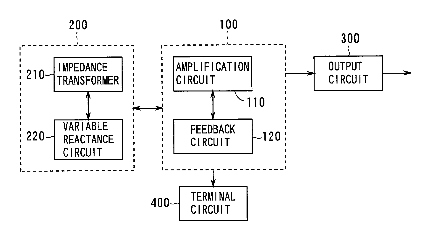
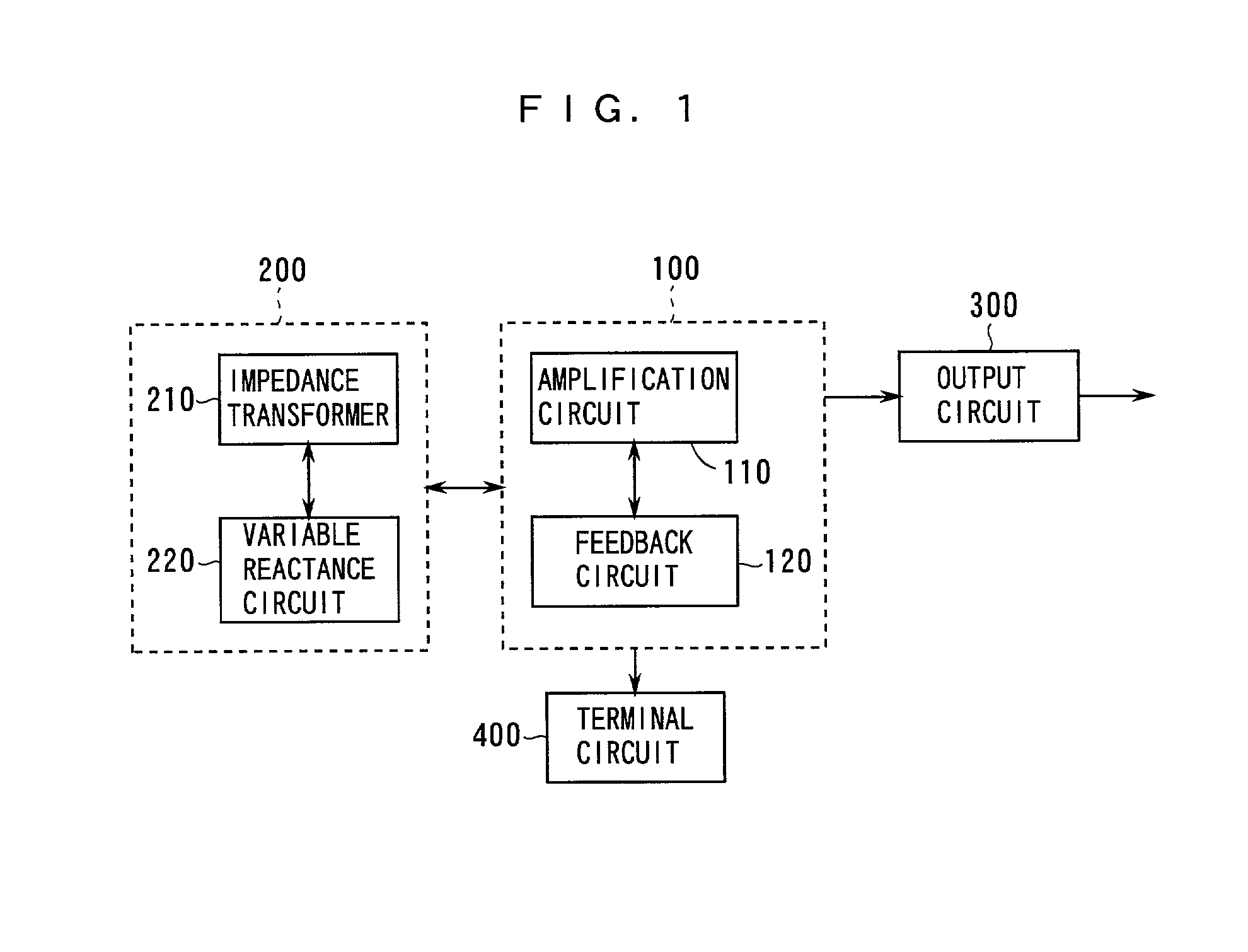
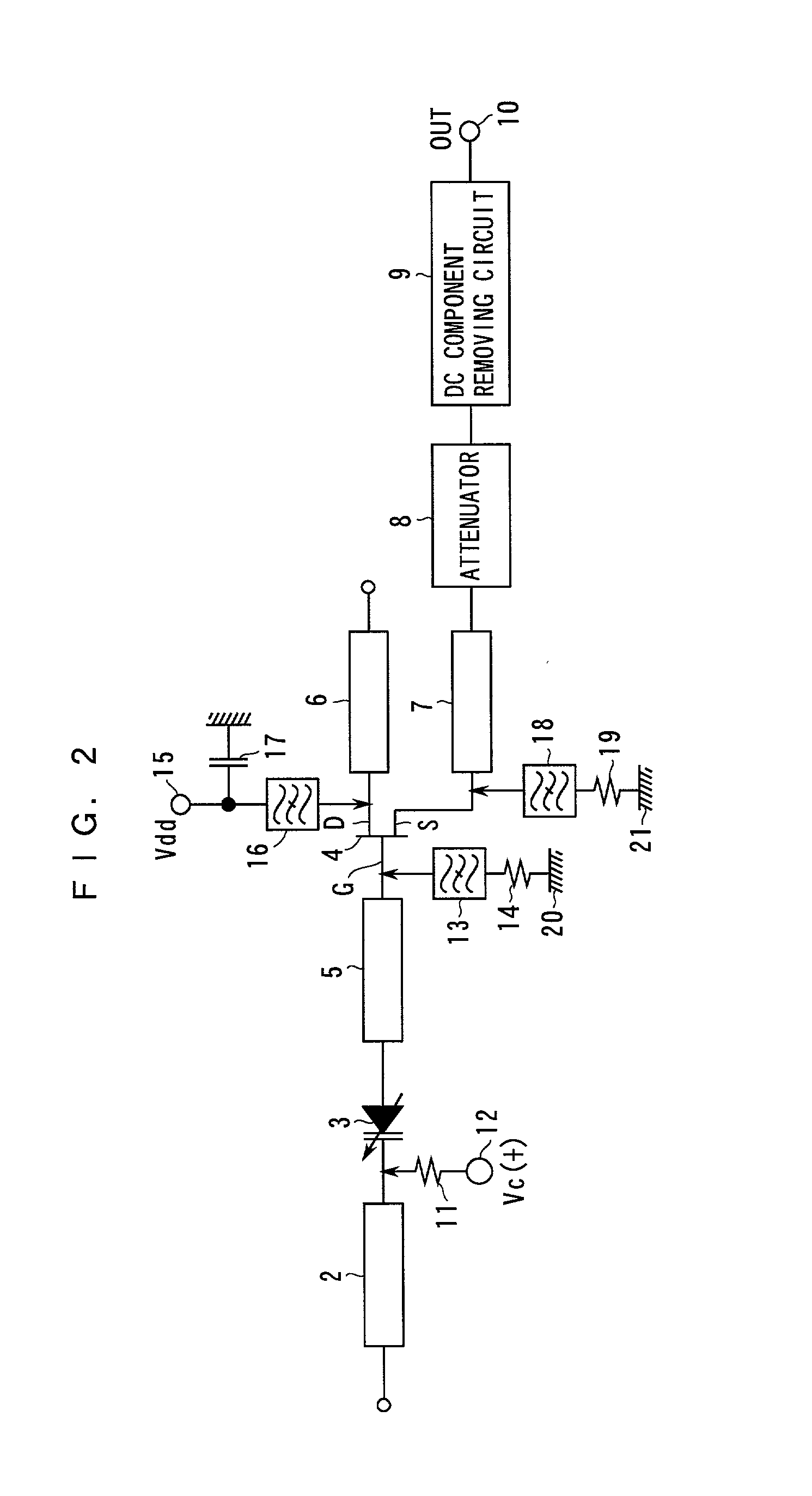
[0008] In the voltage-controlled oscillator according to the present invention, the tuning part resonates in the oscillation frequency band of the oscillation part. When the control voltage is changed, the impedance of the tuning part as viewed from the node between the oscillation part and the tuning part draws a locus including a point where the reactance reaches substantially zero. In this case, the rate of change of the oscillation frequency with respect to change of the control voltage can be increased. The characteristic impedance of the transmission line is so set that the rate of change of the capacitance value of the variable capacitance element with respect to change of the oscillation frequency is minimized within a prescribed range of the characteristic impedance of the transmission line, whereby the rate of change of the oscillation frequency with respect to change of the capacitance value of the variable capacitance element is increased. Therefore, the rate of change of the oscillation frequency with respect to change of the control voltage is so increased that a broadband tuning range can be attained.
[0037] Consequently, fluctuation of communication quality caused by switching of a frequency band or a channel allocated to a communication system is reduced while deterioration of the communication quality resulting from phase noise is reduced.

Problems solved by technology

However, such improvement of the capacity-control voltage characteristic of the varactor diode is too limited to sufficiently broaden the band of the tuning range, sufficiently optimize the tuning range or sufficiently improve the linearity of change of the oscillation frequency with respect to change of the control voltage.

Method used


Image

  • Voltage-controlled oscillator and communication device
  • Voltage-controlled oscillator and communication device
  • Voltage-controlled oscillator and communication device

Examples


Embodiment Construction

, the ratio .alpha. (A / B) was set to 1 by either one of the following two methods, and the electric length .theta..sub.st of the tuning stub 2 was set to (.pi. / 2) rad. The characteristic impedance Z.sub.st of the tuning stub 2 was arbitrary. In this case, the capacity C.sub.n was equal to 1 / .omega..sub.n.sup.2, and the rate of change of the oscillation angular frequency .omega..sub.n was maximized.

[0142] For example, the inductive component A is set to 60 [.OMEGA.] and the fixed capacitor 31 of 1.59 pH is serially added to the varactor diode 3 so that the total of the capacitance values of the varactor diode 3 and the fixed capacitor 31 is 0.265 pH, thereby setting the capacitive component B to 60 [.OMEGA.]. Thus, the inductive and capacitive components A and B are equally set to 60 [.OMEGA.]. Alternatively, the capacitive component B is set to 50 [.OMEGA.] and the inductive component L is set to 0.796 nH by reducing the length of the bonding wire of the variable reactance circuit 2...


PUM


Abstract

An impedance transformer is so designed that the impedance and the reactance of a tuning part reach zero at a central control voltage. An open stub is employed for setting the characteristic impedance of a tuning stub to the minimum value when a variable reactance circuit is inductive while setting the characteristic impedance to -1.22 times the reactance of the variable reactance circuit when the variable reactance circuit is capacitive. A short stub is employed for setting the characteristic impedance of the tuning stub to 0.82 times the reactance of the variable reactance circuit when the variable reactance is inductive, while setting the characteristic impedance to the maximum when the variable reactance circuit is capacitive.

Description

[0001] 1. Field of the Invention[0002] The present invention relates to a voltage-controlled oscillator capable of changing an oscillation frequency by voltage control and a communication device employing the same.[0003] 2. Description of the Background Art[0004] In general, a voltage-controlled oscillator employing a variable capacitance element such as a varactor diode is proposed. In the conventional voltage-controlled oscillator, the capacity-control voltage characteristic of the varactor diode employed as a tuning element is improved for attaining a broadband tuning range (width of change of the oscillation frequency with respect to change of a control voltage), optimizing the tuning range or improving linearity of change of the oscillation frequency with respect to change of the control voltage.[0005] However, such improvement of the capacity-control voltage characteristic of the varactor diode is too limited to sufficiently broaden the band of the tuning range, sufficiently o...

Claims


Application Information

Patent Timeline
IPC IPC(8): H03B5/18
CPCH03B5/1852
Inventor IMAOKA, TOSHIKAZUONODA, KATSUAKI
Owner SANYO ELECTRIC CO LTD
Learn More