Cutting tool and indexable tip

a technology of cutting tool and indexing tip, which is applied in the field of cutting tools, can solve the problems of short machining time, difficult to realize and difficult to achieve the realization of such a combination of requirements

Inactive Publication Date: 2002-07-18
BOEHLERIT GMBH & CO KG
View PDF0 Cites 20 Cited by
  • Summary
  • Abstract
  • Description
  • Claims
  • Application Information

AI Technical Summary

Problems solved by technology

When several machining operations are performed with a single cutting tool, the machining time can be kept short, because expensive changeover times for exchanging cutting tools do not apply.
However, the realization of such a combination of requirements is difficult to achieve.
The indexable tip is shaped such that a change of cutting edges occurs by turning, although the supporting area of the tip is reduced, by which the stability and thus also the surface quality achieved can be substantially impaired.
However, it can be considered detrimental for the tool that can be favorably used for drilling, that with turning and, in particular, an inside turning and die sinking with larger dimensions the largest chip width is limited to half the diameter of the machining section of the tool.
Further, after a single turn of the indexable tip, this must be replaced for cutting edge wear and for cutting edge renewal.
The known cutting tools for drilling into the solid and for turning have the disadvantage in common, that the only machining widths to be achieved with them correspond essentially to the length of the face cutting edge and thus half the diameter of the machining part of the tool.
Although a drilling outside the center optionally allows a slight increase of the bore diameter, this is limited to about 10% of the same.
Experience has shown in operation that variable bore diameters even beyond this size are required, which, however, can only be achieved through the use of several different cutting tools or through an expensive machining technology.
This is linked to a considerable loss of working time.
The uneven distribution of forces thus caused can result in vibrations and stability problems, through which the tool life of the four cutting edges is reduced, and the surface and work piece quality are adversely affected.
It has also been shown that with cutting tools with cutting edges located on the upper side, because of the approximately square shapes of such indexable tips, an incorrect orientation of the same in the tip seat and a subsequent defective attachment can easily occur, particularly if tool users are under pressure, and thus hectic work methods and carelessness often result.
Although attempts are made to prevent defective attachment and the consequent dangers for user and tool by additionally attaching signs on such indexable tips, such dangers cannot be ruled out.

Method used


Image

  • Cutting tool and indexable tip
  • Cutting tool and indexable tip
  • Cutting tool and indexable tip

Examples


Embodiment Construction

[0064] The particulars shown herein are by way of example and for purposes of illustrative discussion of the embodiments of the present invention only and are presented in the cause of providing what is believed to be the most useful and readily understood description of the principles and conceptual aspects of the present invention. In this regard, no attempt is made to show structural details of the present invention in more detail than is necessary for the fundamental understanding of the present invention, the description taken with the drawings making apparent to those skilled in the art how the several forms of the present invention may be embodied in practice.

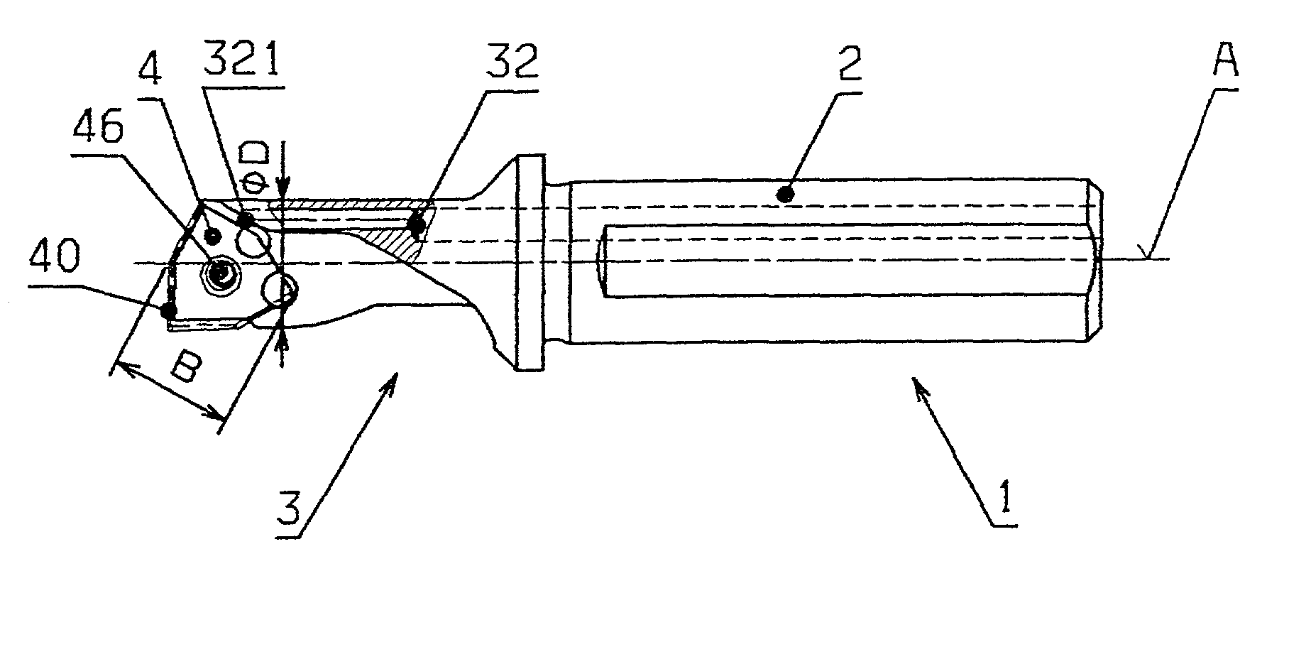
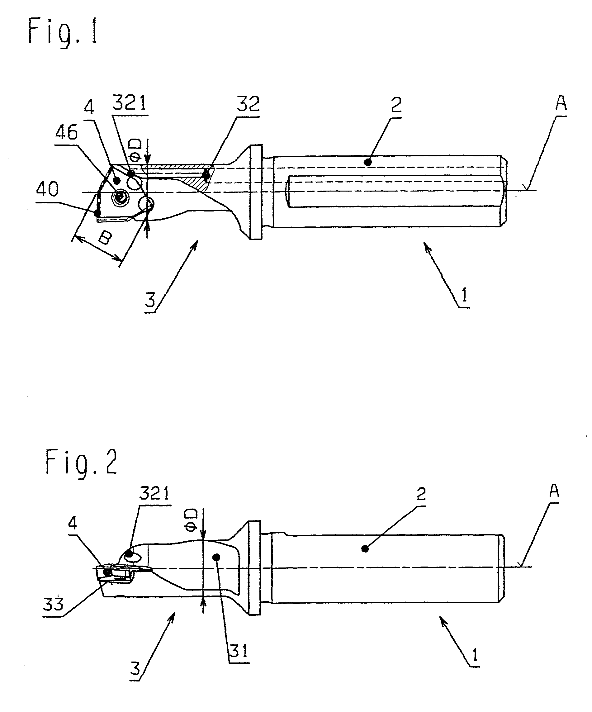
[0065] In FIG. 1, a cutting tool according to the invention is shown in plan view by way of example. Such a cutting tool includes essentially a base body 1 with a clamping part 2 and a working part 3 following it in an axial direction. A coolant channel 32 passes through base body 1 in the direction of the axis of rotati...


PUM

PropertyMeasurementUnit
angleaaaaaaaaaa
angleaaaaaaaaaa
angleaaaaaaaaaa

Abstract

Cutting tool for drilling and turning. The cutting tool includes a base body having a clamping part and a working part axially spaced from each other, and an indexable tip, releasably connected to the working part, having a hexagonal shape having at least one circumferential cutting edge and obtuse and acute corner angles.

Description

[0001] The present application claims priority under 35 U.S.C. .sctn.119 of Austrian Patent Application No. 88 / 2000, the disclosure of which is expressly incorporated by reference herein in its entirety.[0002] 1. Field of the Invention[0003] The present invention relates to a cutting tool for drilling and turning. The tool includes a base body having at least one coolant bore, as well as a clamping part and an essentially cylindrically formed working part following the clamping part in an axial direction. An indexable tip, which is releasably connected to the working part at its end opposite the clamping part, includes, in plan view, circumferential cutting edges. The working part has a flute running in the direction of the tool axis and a form-locking seat for the indexable tip with cutting edges slightly projecting.[0004] Further, the invention relates to an indexable tip for a cutting tool for machining materials, in particular metals and alloys. The indexable tip is limited by a...

Claims


Application Information

Patent Timeline
Patent Type & Authority Applications(United States)
IPC IPC(8): B23B27/00B23B27/14
CPCB23B27/007B23B27/141B23B2200/0409Y10T407/22Y10T407/235Y10T407/23
Inventor SCHLEMMER, ARMINMELCHER, GERHARD
Owner BOEHLERIT GMBH & CO KG
Why Eureka
Try Eureka