Valve timing control device

Inactive Publication Date: 2002-09-05
MITSUBISHI ELECTRIC CORP
View PDF0 Cites 18 Cited by
  • Summary
  • Abstract
  • Description
  • Claims
  • Application Information

AI Technical Summary

Benefits of technology

0014] The lock hydraulic pressure may be set to be nearly equal to or lower than a hydraulic pressure of generating a torque generated in the device, the torque being equal to a cam-torque during internal-combustion. In this way, even under a minimum hydraulic pressure condition

Problems solved by technology

However, the intermediate position lock type of the valve timing control device has typical problems derived from the typical construction, which is different from the conventional valve timing control devices such as the maximum advanced side position lock type or the maximum retarded side position lock type.
A hydraulic pressure in the advance side hydraulic pressure chamber or the retardation side hydraulic pressure chamber and a release hydraulic pressure chamber is therefore substantially reduced to one half of the hydraulic pressure in the OCV and the release hydraulic pressure is not sufficient.
In this case, there is a problem that the lock member and the fitting hole undergo wear which reduces their durability, and that the valve timing control device becomes incapable of operation from the intermediate retained state.
Second, when the lock member is operated beyond the fitting hole as the intermed

Method used


Image

  • Valve timing control device
  • Valve timing control device
  • Valve timing control device

Examples


first embodiment

[0034] Hereafter, the present invention will be explained.

embodiment 1

[0035] Embodiment 1

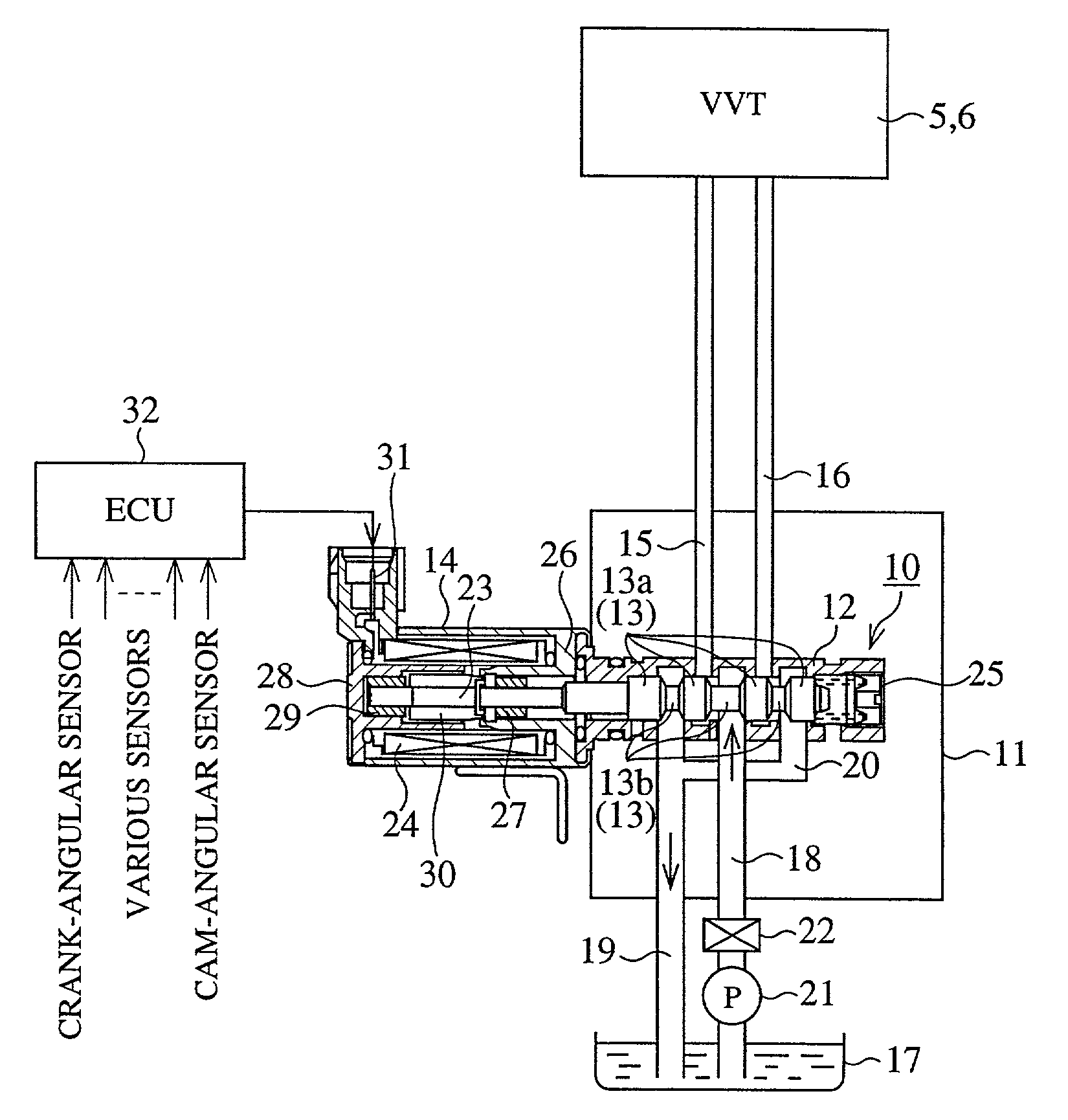
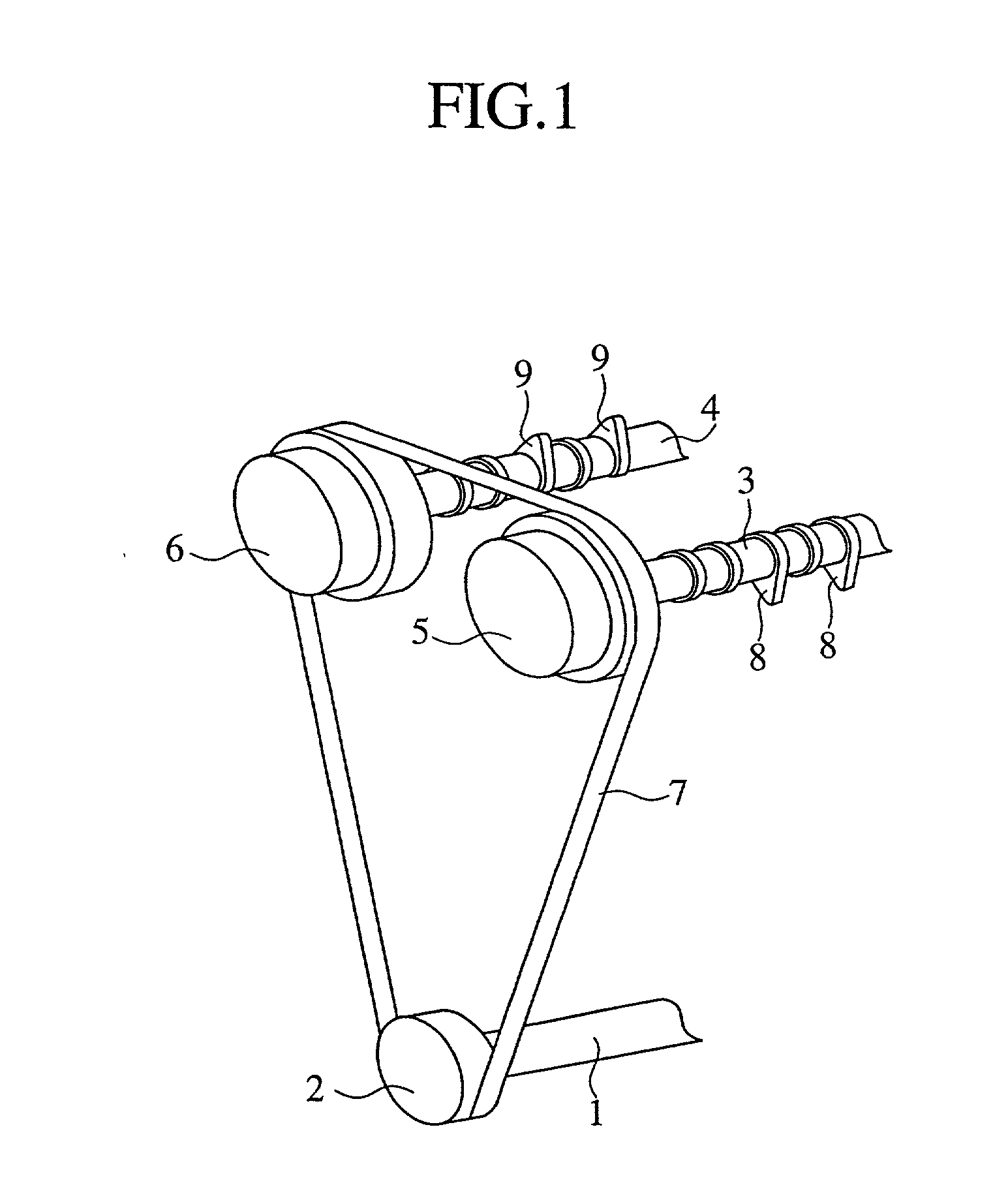
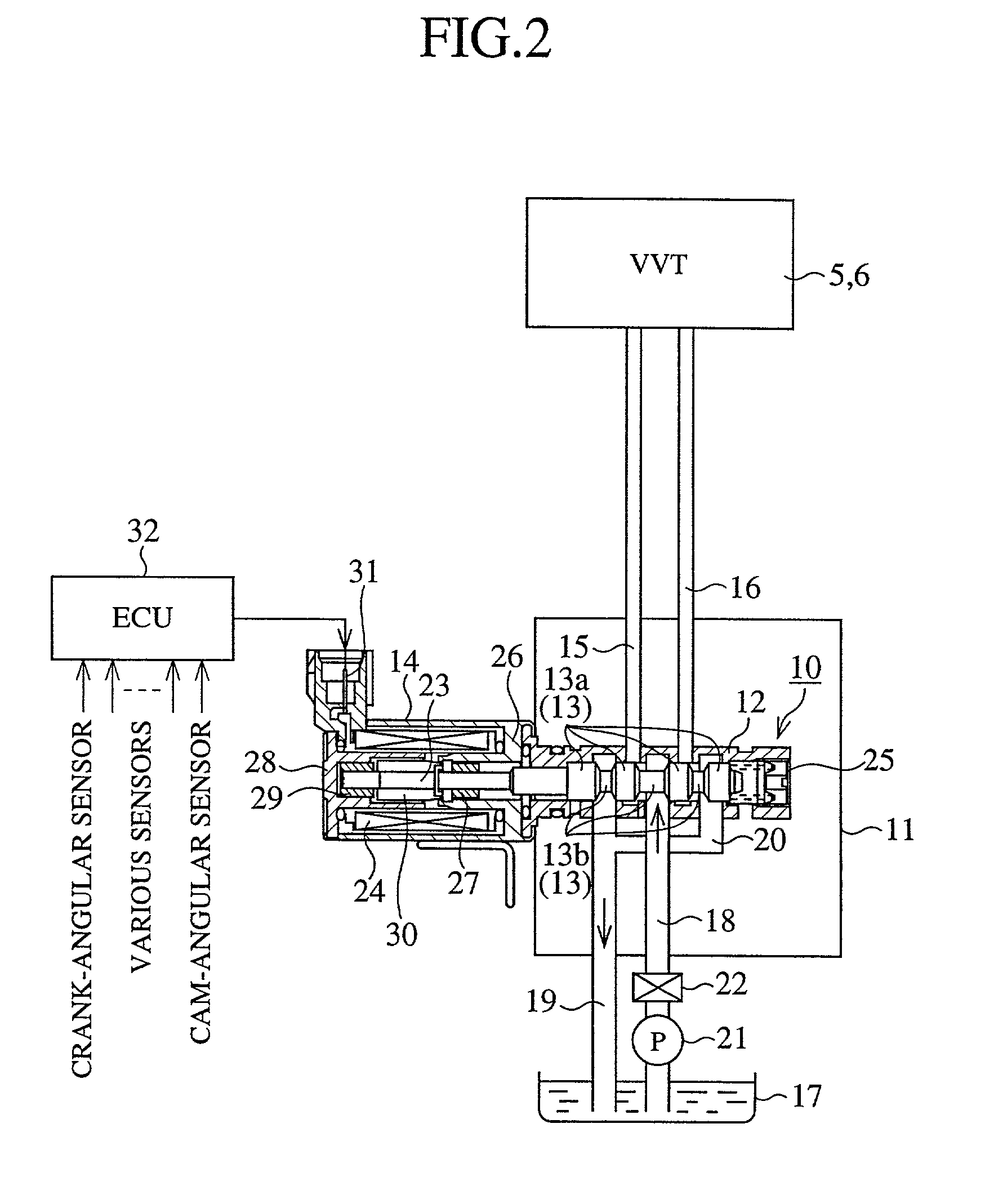
[0036] FIG. 1 is a perspective view of a valve system of the engine equipped with a valve timing control device according to the present invention. FIG. 2 is a partial cross sectional view of an internal construction of an oil control valve for supplying a hydraulic pressure to the valve timing control device shown in FIG. 1. FIG. 3 is a lateral cross sectional view of an internal construction of a valve timing control device as embodiment 1 according to the present invention. FIG. 4 is a cross sectional view taken along lines A-A of FIG.3. FIG. 5 is an enlarged cross sectional view of a main point B of FIG. 4. FIG. 6 is a graph showing a relation of a release hydraulic pressure and an operation of the lock member in the valve timing control device shown in FIG. 3, FIG. 4 and FIG. 5.

[0037] In FIG. 1, reference numeral 1 denotes a crankshaft of an engine (not shown) and numeral 2 denotes a chain sprocket fixed on an end of the crankshaft 1. Numeral 3 denotes an int...

embodiment 2

[0068] Embodiment 2

[0069] FIG. 7 is a lateral cross sectional view of an internal construction of a valve timing control device as embodiment 2 according to the present invention. Components of the embodiment 2 of the present invention which are the same as those of the embodiment 1 are denoted by the same reference numerals and further description will be omitted.

[0070] In FIG. 7, a hydraulic pressure switch valve 54 includes a valve groove 54a, an approximately cylindrical-shaped valve body 54b, an advance side communication groove 54c and a retardation side communication groove 54d. The valve groove 54a is formed at an end face of the housing 40 close to the case 41 and has an about ellipse-shaped inner space. The valve body 54b is accommodated in the valve groove 54a. The advance side communication groove 54c is formed at the end face of the housing 40 close to the case 41 to communicate between the valve groove 54a and the advance side hydraulic pressure chamber 43. The retarda...


PUM


Abstract

A valve timing control device includes a lock member and a push member. The lock member locks a rotor in relation to a case at an approximately intermediate position apart from both of the maximum advanced side position and the maximum retarded side position. At all times, the push member pushes the lock member in a direction-of fitting the lock member in the fitting hole arranged at any one hand of the rotor or the case. A release hydraulic pressure for releasing the fitting state of the lock member in the fitting hole against the push force of the push member is set to be higher than a lock hydraulic pressure for allowing the fitting state of the lock member in the fitting hole.

Description

[0001] 1. Field of the Invention[0002] The present invention relates to a valve timing control device for modifying the opening and closing timing of an intake valve or an exhaust valve making contact with cams fixed on an intake camshaft or an exhaust camshaft of an internal-combustion engine (hereafter, referred as an engine).[0003] 2. Description of the Prior Art[0004] Various types of solutions have been proposed for conventional valve timing control devices. The majority of the proposition includes a housing of rotating in synchronization with a driving force transmitting means transmitting a driving force from a crankshaft of the engine to an intake camshaft and an exhaust camshaft, a case fixed on the housing and having a plurality of shoes which are projected inwardly to form a plurality of hydraulic pressure chambers, and a rotor fixed on an end of the intake camshaft or the exhaust camshaft and having a plurality of vanes to divide the hydraulic pressure chambers into adva...

Claims


Application Information

Patent Timeline
IPC IPC(8): F01L1/344F01L1/34
CPCF01L2001/3444F01L2001/34453F01L1/3442F01L2001/34426
Inventor HASE, HIROFUMI
Owner MITSUBISHI ELECTRIC CORP
Why Eureka
Try Eureka