Radiant heater

Inactive Publication Date: 2002-09-05
E G O ELEKTRO GERAETEBAU GMBH
View PDF0 Cites 17 Cited by
  • Summary
  • Abstract
  • Description
  • Claims
  • Application Information

AI Technical Summary

Benefits of technology

[0008] The fastening means preferably comprise a holder for holding the sensor and an abutment for securing the holder. Compared with the holder portion extending through the insulator, the abutment advantageously has a different configuration. Thus, it is possible for the abutment to be inclined or to be substantially transversely directed. Thus, e.g. a holding leg of the holder can be bent at right angles behind the insulator in order to prevent extraction. The holder is preferably retained by engaging the abutment with its entire or a large surface against the underside of the insulator. This reduces or eliminates the risk of the fastening being torn out of the insulator.
[0015] One possibility for connecting the holder to a metal carrier shell is the welding or riveting of corresponding components. Preferably the holder is joined to or worked out from the carrier shell in one piece. This makes it possible to rough-work an elongated sheet metal strip separated by three notches, which form a U, from the carrier shell and bend or set up the same. The insulator can be engaged over the holder or at least one leg thereof. In particular during the fitting of the radiant heater, the holder can automatically pierce the insulator, at least partly project over the same and receive the sensor. Either the holder can pass through the insulator on engaging the latter or can project through a prefabricated slot in the insulator.
[0017] This makes it possible with radiant heaters having planar carrier shells to easily and advantageously stack the same, because the underside or the carrier shell is not projected over by interfering abutments or the like. In certain circumstances it is advantageously possible to economize the costs involved in providing the carrier shell from below with a recess for receiving the abutment.

Problems solved by technology

Inter alia such a sensor fastening ensures that the sensor does not strike against the glass ceramic plate, which could lead to the breakage of the latter.

Method used


Image

  • Radiant heater
  • Radiant heater
  • Radiant heater

Examples


Embodiment Construction

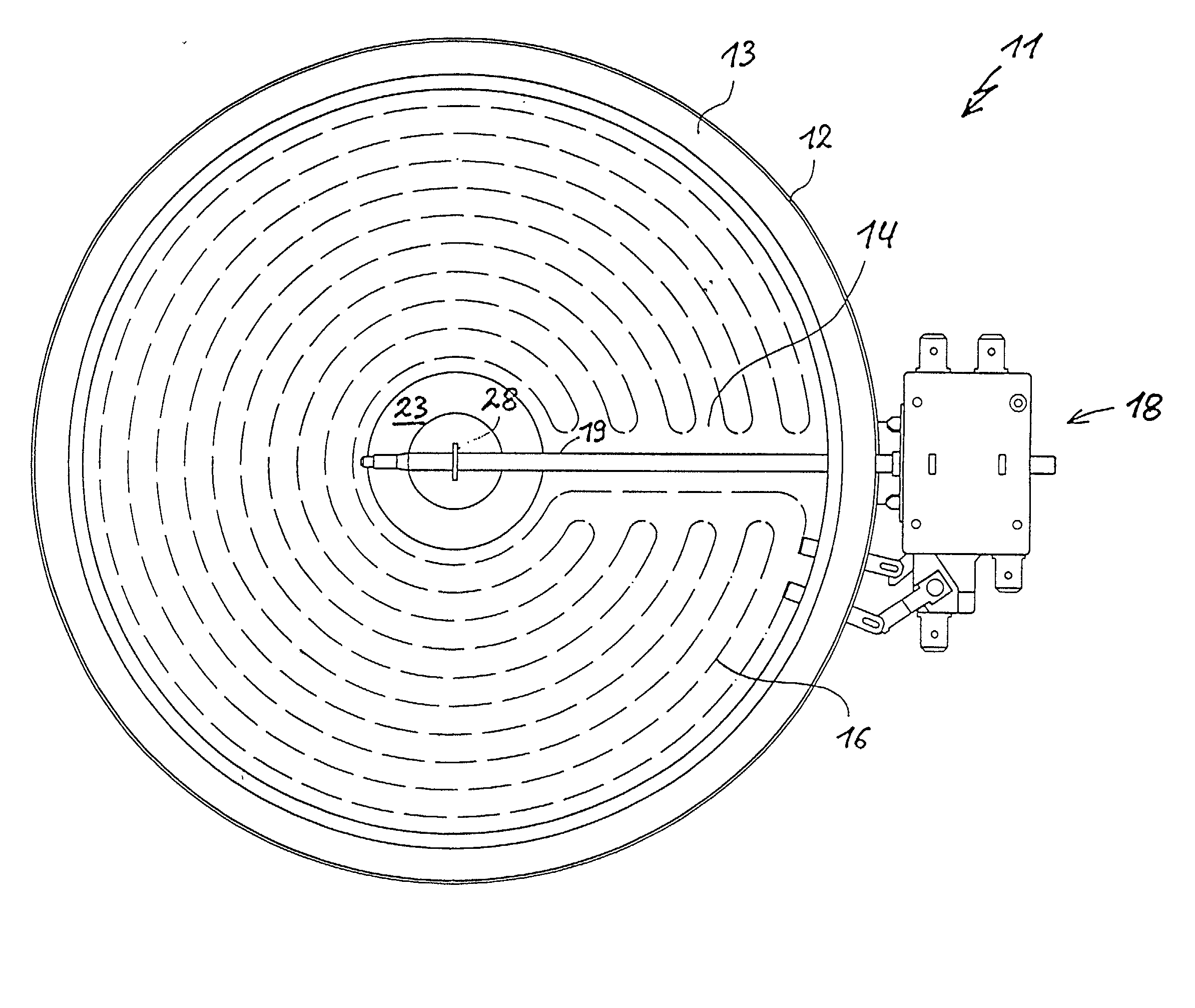
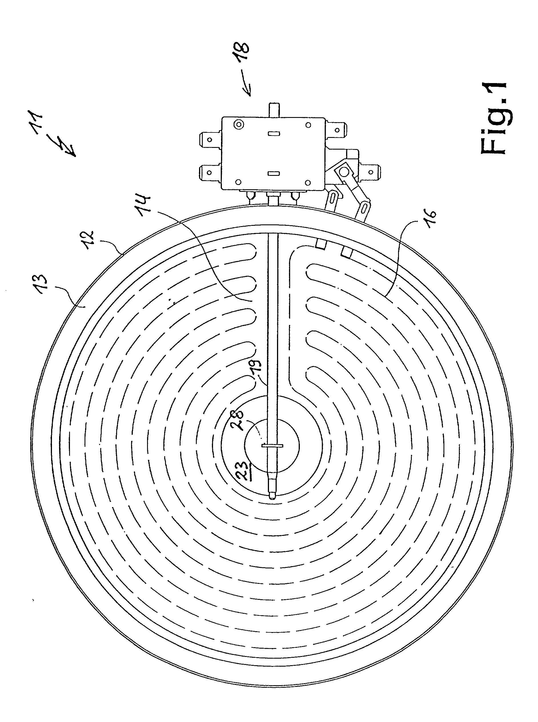
[0029] FIG. 1 shows in plan view a radiant heater 11 in which an insulating border 13 and a flat insulator 14 are inserted in a carrier shell 12. The insulator 14 covering the bottom of the carrier shell 12 carries a heating means 16 comprising an elongated, meandering heating band or the like. The heating means 16 is electrically connected by means of a terminal or a thermal relay 18, which switches off the radiant heater 11 or heating means 16 in the case of an excessive temperature. For this purpose the thermal relay 18 has an elongated sensor 19 extending into the radiant heater 11 and which in known manner is made from materials having different thermal expansion coefficients and in particular one in rod-like form and the other surrounding it in tubular manner. The sensor 19 covers part of the heating zone formed by the heating means 16 and which essentially takes up the surface or area of the insulator 14. The sensor 19 extends by a portion over the centre of the radiant heate...


PUM


Abstract

According to an exemplary embodiment of the invention a radiant heater (11) for a glass ceramic cooking area (25) is created. The radiant heater comprises a carrier shell (12) carrying a flat insulator (14), on which is placed a heating means (16). A thermal relay (18) projects with its tube-like sensor (19) into the central area of the radiant heater (11) and the sensor can rest on an elevation (23) of the insulator (14). By means of a holder (45) the sensor (19) can be fixed to the carrier shell (12). The holder does not project over the underside of the carrier shell (12). In one embodiment the holder with barb-like ends reaches into an opening in the carrier shell and is fixed to locking edges of the carrier shell.

Description

FIELD OF APPLICATION AND PRIOR ART[0001] The invention relates to a radiant heater. The invention specifically relates to a radiant heater for placing beneath a cooking area, particularly a tempered glass or glass ceramic plate, having a carrier shell, which carries an insulator, on and / or in which is located a heater forming a heating zone, and with at least one elongated temperature sensor of a protective switch projecting over part of the heating zone and running between the latter and the cooking area, the sensor being retained by the insulator and fastening means reaching the carrier shell.[0002] Such radiant heaters conventionally have a temperature sensor, whose outer tube is made from an insulating material, particularly quartz or quartz glass. It is either incorporated into the expansion system of the sensor, in which it forms a tube with a low expansion coefficient, in which is located a tension bar with a higher expansion coefficient, or it is shoved onto an expansion tub...

Claims


Application Information

Patent Timeline
Patent Type & Authority Applications(United States)
IPC IPC(8): H05B3/74
CPCH05B3/74H05B3/746H05B3/748
Inventor PETRI, HEINZWILDE, EUGENBELZ, BERNHARDMOHR, HANSJENZ, ULRICH
Owner E G O ELEKTRO GERAETEBAU GMBH
Why Eureka
Try Eureka