
System of securement of dental abutments to dental implants

a technology of dental abutments and dental implants, which is applied in the field of dental abutments securement system of dental implants, can solve the problems of little assistance, patient discomfort, and vulnerability to loosening, and achieve the effects of ensuring long-term stability of the abutment, reducing the potential for development, and increasing comfort for patients

Inactive Publication Date: 2002-09-05
PILLA NICOLA +3
View PDF4 Cites 28 Cited by
  • Summary
  • Abstract
  • Description
  • Claims
  • Application Information

AI Technical Summary

Benefits of technology

[0010] It is accordingly an object of the present invention to provide an improved means of securing a dental abutment to its corresponding dental implant.
[0011] It is another object to provide a means of securement between an abutment and an implant, which will assure long-term stability of the abutment and its associated dental restoration, relative to the implant and, thereby, increased comfort to the patient.
[0012] It is a further object to provide a system of the above type, which will minimize the potential for the development of microscopic bacteria-containing crevices between the abutment and implant.
[0013] It is thereby a yet further object of the invention to provide a system of securement of dental abutments of the above type that will reduce the possibility of gum disease resultant from long term weakening of the implant-abutment interface.

Problems solved by technology

A longstanding problem in the area of implant dentistry has been that of effecting reliable securement of the abutment of a dental restoration to an implant which has been embedded within the jaw of a patient.
This technique, which is as old as implant dentistry itself, has suffered from vulnerability to loosening by reason of the accumulated effect, over time, of microscopic rotation and counter-torquing of the abutment relative to the implant.
Such loosing of the prosthesis can cause discomfort to the patient.
Therefore, as a practical matter, the tortional forces, to which an abutment is subjected during normal use of a restoration by a patient, are such that the narrow annular interface of the locking screw to abutment screw of Gordon will provide very little assistance in maintaining the head of the abutment screw in a stable position relative to the bottom shoulder or seat of the abutment channel and relative to the implant itself.

Method used


Image

  • System of securement of dental abutments to dental implants
  • System of securement of dental abutments to dental implants
  • System of securement of dental abutments to dental implants

Examples


Embodiment Construction

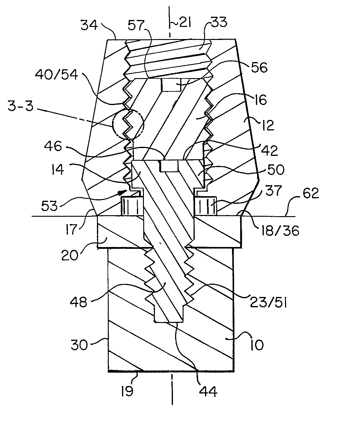
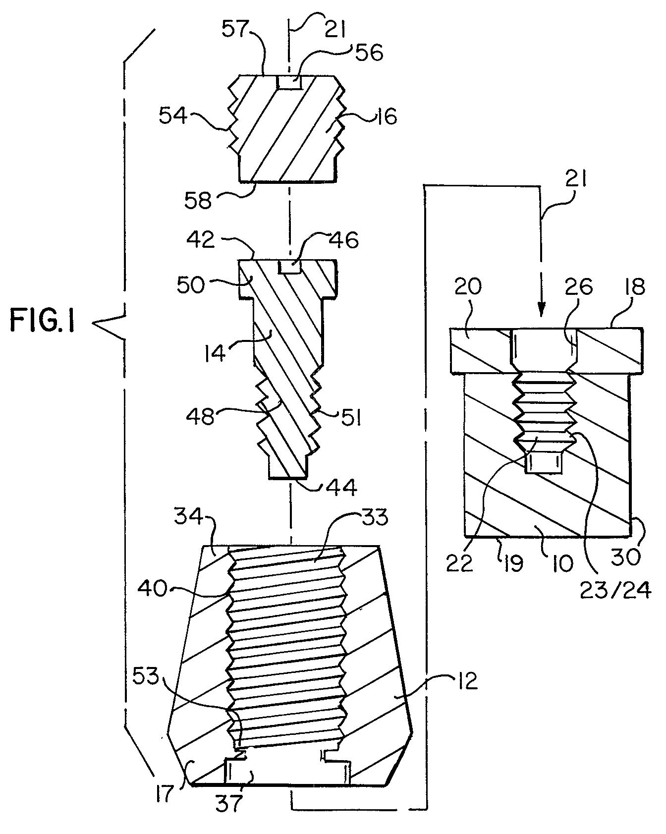
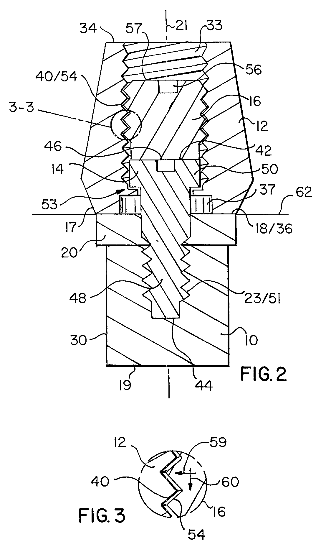
[0018] With reference to the exploded view of FIG. 1, the components of the instant system for securement of dental abutments may be seen to include a dental implant 10, a dental abutment 12, an abutment securement screw 14, and a locking screw 16. A tapered surface 17 is termed the cuff of the abutment, a distal surface of which also comprises a distal surface 36 of said abutment.

[0019] As may be further noted with reference to FIGS. 1 and 2, the dental implant 10 includes a proximal end surface 18, distal end surface 19 and a collar 20, all of which surfaces are radially symmetric about a system axis 21, which is also an axis of rotation of both the implant 10 and the abutment 12. Said implant includes an axial channel 22 having a threaded portion 24 and an unthreaded portion 26. It is, thereby, to be appreciated that axially directed channel 22 must be at least partially threaded. It is further noted that threadings 23 of threaded portion 24 of implant channel 22 are characterize...


PUM


Abstract

A system for tooth implantation having an implant part to be set into the jawbone, and an abutment part to which a tooth restoration is attached. The abutment part is screwed onto the implant part by an abutment screw, and a locking screw is disposed to lock the abutment screw to secure the abument part to the implant part to prevent loosening of the abutment. The threading interface between the lock screw and an abutment channel is matched in spiral direction but mismatched in thread timing with an interface between said abutment screw and an implant channel, thereby generating radial and axial locking forces.

Description

REFERENCE TO RELATED APPLICATION[0001] This case is a continuation-in-part of application Ser. No. 09 / 429,106, filed Oct. 28, 1999.[0002] (c), (d)[0003] N / A(e) BACKGROUND OF THE INVENTION[0004] A longstanding problem in the area of implant dentistry has been that of effecting reliable securement of the abutment of a dental restoration to an implant which has been embedded within the jaw of a patient.[0005] In the prior art, securement of an abutment to its implant has typically been effected through the use of a screw to screw thread channel connection from the abutment to the implant, that is, through the use of a torquable screw head of an Allen Head type having a shank threaded into a complementally threaded co-axial channel within the dental implant. This technique, which is as old as implant dentistry itself, has suffered from vulnerability to loosening by reason of the accumulated effect, over time, of microscopic rotation and counter-torquing of the abutment relative to the i...

Claims


Application Information

Patent Timeline
IPC IPC(8): A61C8/00
CPCA61C8/005A61C8/0068
Inventor PILLA, NICOLANILO, PATRICIOHOLLANDER, BRUCE L.OHANA, GILBERT
Owner PILLA NICOLA
Learn More