Image forming apparatus

a technology of image forming apparatus and image memory, which is applied in the direction of instrumentation, photomechanical treatment, colour separation/tonal correction, etc., can solve the problems of inappropriate printing, many times of inappropriate printing, and the inability to execute image memory in a suitable image formation condition, etc., to achieve speedily the effect of density correction

Inactive Publication Date: 2006-08-03
SHARP KK
View PDF11 Cites 16 Cited by
  • Summary
  • Abstract
  • Description
  • Claims
  • Application Information

AI Technical Summary

Benefits of technology

[0015] The objective of the present invention is to provide an image forming apparatus that can s

Problems solved by technology

The above-described conventional arrangement causes the following problem, in a case where the density correction condition is satisfied while the printing is carried out.
However, in this case, if the image memory stores another job when the density correction condition is satisfied, said another job stored in the image memory is not executed in a suitable image formation condition.
This problem occurs on account of disagreement between (i) the image processing (gamma process and screen process) to which the job is subjected and (ii) the image formation condition at the time of executing the print job.
The printing is therefore not carried out in suitable image formation condition.
This p

Method used


Image

  • Image forming apparatus
  • Image forming apparatus
  • Image forming apparatus

Examples


embodiment 1

[0035] The following will describe an embodiment of the present invention in reference to figures. First, the outline of an image forming apparatus of the present embodiment is described in reference to FIG. 2.

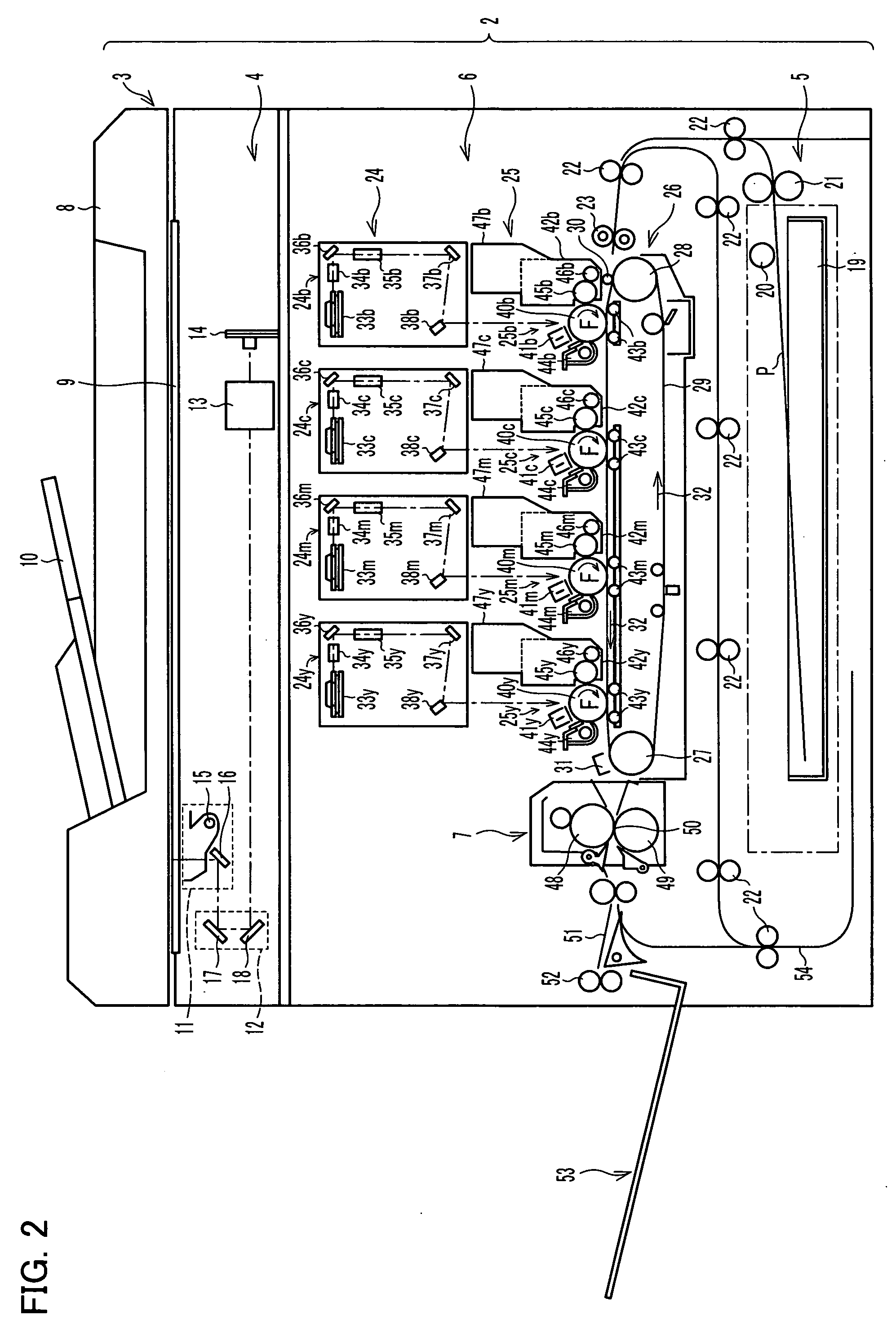
[0036]FIG. 2 shows a photocopier 2 which is a type of the image forming apparatus. The photocopier 2 includes a document supply section 3, an image reading section 4, a paper feeding section 5, an image forming section 6, and a fixing section 7.

[0037] The document supply section 3 includes a reversing automatic document feeder (abbreviated as RADF) 8, a document supporter 9 on which a document supplied from the RADF 8 is provided in a predetermined position, and a document receiving tray 10. There is a certain positional relationship between the RADF 8 and the document supporter 9, and the RADF 8 is supported in such a manner as to be openable and closable. The RADF 8 supplies a document in such a manner that one surface of the document is placed at a predetermined position ...

embodiment 2

[0079] The following will describe another embodiment of the present invention with reference to figures. The description on an image forming apparatus of the present embodiment is omitted, because it is basically identical with the image forming apparatus of FIG. 2.

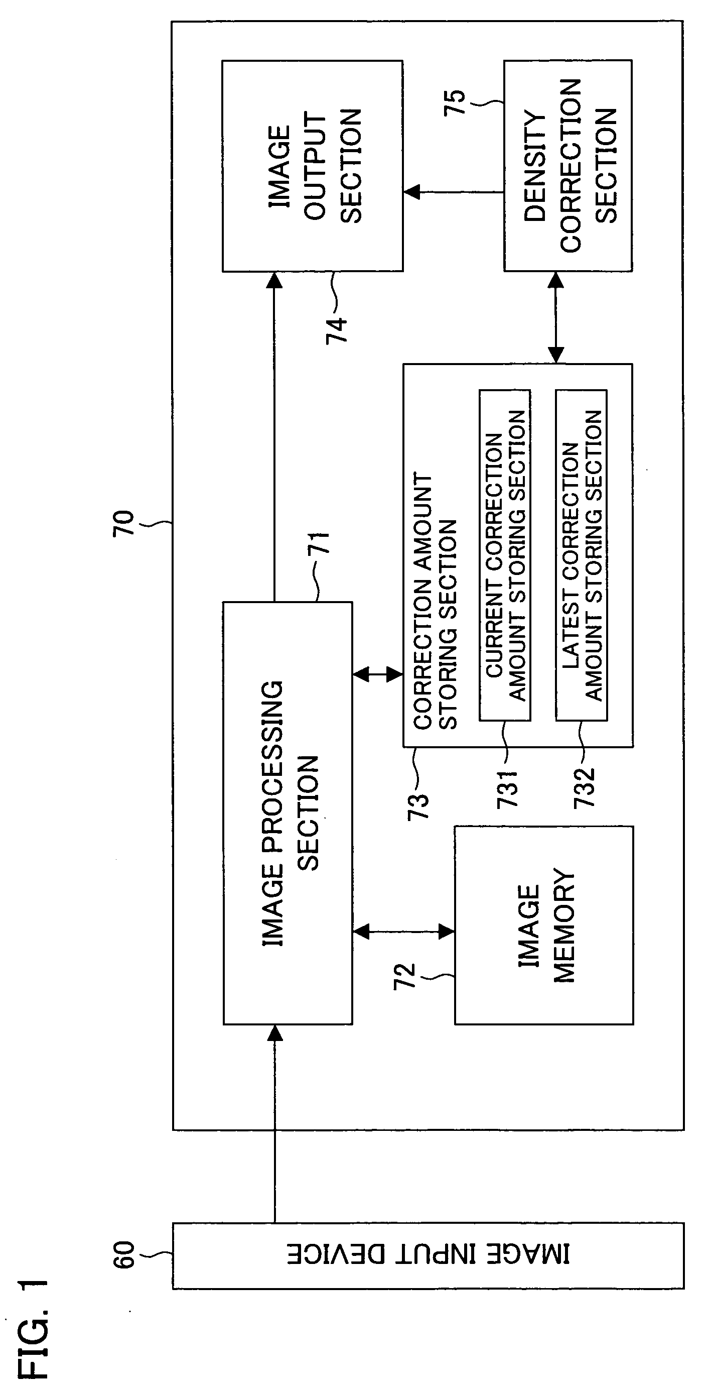
[0080] The image forming apparatus of the present embodiment forms images by electrophotography, and includes an image memory that can store a plurality of jobs. Also, the image forming apparatus of Embodiment 2 can form color images. As an embodiment of the image forming apparatus of the present invention, FIG. 5 shows a digital color multifunction device. As shown in FIG. 5, the digital color multifunction device includes an image input device 60 and an image output device 80.

[0081] The image input device 60 in this embodiment may be identical with that of Embodiment 1, and the image input device 60 supplies image data to the image output device 80. In Embodiment 2, the image input device 60 is capable of outputting ...

embodiment 3

[0100] The following will describe a further embodiment of the present invention in reference to figures. An image forming apparatus of the present embodiment is basically identical with the image forming apparatus of FIG. 2. Detailed description of the image forming apparatus of the present embodiment is therefore omitted.

[0101] The image forming apparatus of the present invention forms images by electrophotography, and includes an image memory that can store a plurality of jobs. As an embodiment of the image forming apparatus of the present invention, FIG. 7 shows a digital color photocopier. As shown in FIG. 7, the digital color photocopier includes an image input device 60 and an image output device 90.

[0102] The image input device 60 may be identical with that of Embodiment 1, and the image input device 60 supplies image data to the image output device 90. The image output device 90 performs predetermined image processing with respect to image data supplied from the image inp...


PUM


Abstract

In a case where the density correction condition of an image output section is satisfied while a job is being executed, density correction means performs density correction while the job is being executed or after the execution of the job. On this occasion, if there is a job on standby for printing in an image memory, this job is executed in the image formation condition (i.e. a correction amount stored in a current correction amount storing section) determined before the density correction. In the meanwhile, a job which is stored after the density correction is executed in a latest image formation condition (i.e. a correction amount stored in a latest correction amount storing section) which is figured out by the aforesaid density correction.

Description

[0001] This Nonprovisional application claims priority under 35 U.S.C. § 119(a) on Patent Application No. 033654 / 2005 filed in Japan on Feb. 9, 2005, Patent Application No. 027051 / 2005 filed in Japan on Feb. 2, 2005, and Patent Application No. 027049 / 2005 filed in Japan on Feb. 2, 2005, the entire contents of which are hereby incorporated by reference. FIELD OF THE INVENTION [0002] The present invention relates to an electrophotographic image forming apparatus such as photocopiers and printers, and particularly relates to an image forming apparatus that detects conditions for density correction while image formation (printing) is carried out, and performs the density correction when the density correction condition is satisfied. BACKGROUND OF THE INVENTION [0003] In electrophotographic image forming apparatuses, the image quality (density) of a printed matter changes because the apparatus changes over time, e.g. the deterioration of a photoconductor. Therefore, to stably perform the...

Claims


Application Information

Patent Timeline
IPC IPC(8): G03F3/08
CPCH04N1/00002H04N1/00015H04N1/00023H04N1/00031H04N1/00045H04N1/0005H04N1/00055H04N1/00063H04N1/00087H04N1/00954H04N1/40006
Inventor KITAGAWA, TAKASHIIMAGAWA, SHINJITANAKA, TATSUYAKAWANO, HIROSHITAKA, KYOSUKE
Owner SHARP KK
Why Eureka
Try Eureka