Optical fiber coupler

a technology of optical fiber and coupler, applied in the field of optical fiber coupler, can solve the problems of reducing the efficiency of coupling by 20%, highest precision, and previously known fiber couplers are extremely expensive in their production, and achieves compact structure, high production efficiency, and long-term stability. the effect of precision and long-term stability

Active Publication Date: 2008-01-22
TOPTICA PHOTONICS AG
View PDF14 Cites 2 Cited by
  • Summary
  • Abstract
  • Description
  • Claims
  • Application Information

AI Technical Summary

Benefits of technology

[0008]Against this background, it is an object of the present invention to provide an improved fiber coupler, which allows adjustment of the focusing lens or the fiber, respectively, in the axial or transversal direction, respectively, with sufficient precision and long-term stability. In addition, the coupler should be compact in structure and inexpensive to produce.
[0010]In the case of the fiber coupler according to the invention, the adjustability of the fiber or of the focusing lens, respectively, is based on the use of elastic monolithic joints. Because of the elastic properties of the monolithic joints, the setting mechanism needed for the fiber coupler can be implemented in particularly simple manner. Setting is simple because in order to make an adjustment, a force has to be exerted merely in one direction, counter to the elastic reset force of the joint. The reset force then automatically assures the long-term stability of the adjustment. The fiber coupler according to the invention has the advantage that the holder elements and the related base bodies can be produced in one piece with one another (monolithic) so that each holder element is integral with its associated base body. For this purpose, known electro-erosion methods, such as wire erosion, for example, can be used. The fiber coupler according to the invention therefore can be produced both cost-effectively and compactly.
[0012]In order to adjust the focusing lens or the fiber, respectively, essentially parallel to the optical axis, it is practical if one of the holder elements is connected with the base body by way of a total of four monolithic joints and two lever arms, whereby the two lever arms are disposed in the manner of a parallelogram. By means of the arrangement in the shape of a parallelogram, an essentially linear movement is implemented. Tilting or turning of the focusing lens or of the fiber is avoided. All that occurs is an extremely slight parasitic arc movement of the holder element, but this movement has no noticeable effects if the stroke of the linear movement as a whole is limited.
[0014]In the fiber coupler according to the invention, an adjustment possibility in the axial or transversal direction, respectively, can be implemented in particularly simple manner. Such adjustment is made possible by an adjustment screw for fixing the position of the holder element relative to the base body, which screw engages on at least one of the holder elements. By means of this adjustment screw, a force counter to the elastic reset force of the monolithic joint acts on the corresponding holder element. Therefore, one adjustment screw is sufficient for adjustment for each adjustment direction, since this screw, interacting with the elastic properties of the monolithic joint, will determine the position of the holder element and, at the same time, fix it in place.

Problems solved by technology

A deviation from the optimal position of only one micrometer in the transversal direction reduces the efficiency of the coupling by 20%.
It is a disadvantage of the aforementioned fiber coupler that it consists of a plurality of mechanical components for the various setting members, which must be produced with the greatest precision.
For this reason, the previously known fiber coupler is extremely expensive in its production.
It is a further disadvantage that the gear mechanism described above can hardly be produced with sufficient precision for the axial adjustment of the focusing lens, in order to satisfy the requirements for fiber couplers used with single mode fibers, as mentioned above.
Another disadvantage results from the complicated mechanical design of the previously known fiber coupler.
It is a disadvantage that the structure of the coupler is not very compact.
Finally, another disadvantage is the insufficient precision in the adjustment of the lens or the fiber end in the transversal direction, respectively, as well as the poor long-term stability of the adjustment.

Method used


Image

  • Optical fiber coupler
  • Optical fiber coupler
  • Optical fiber coupler

Examples


Embodiment Construction

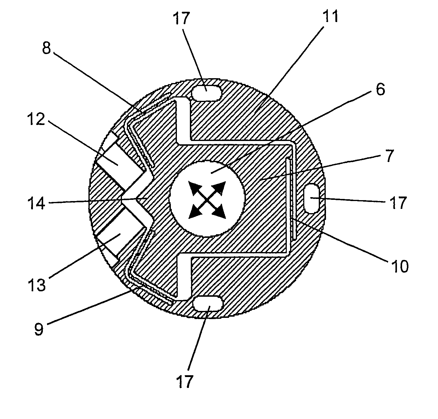
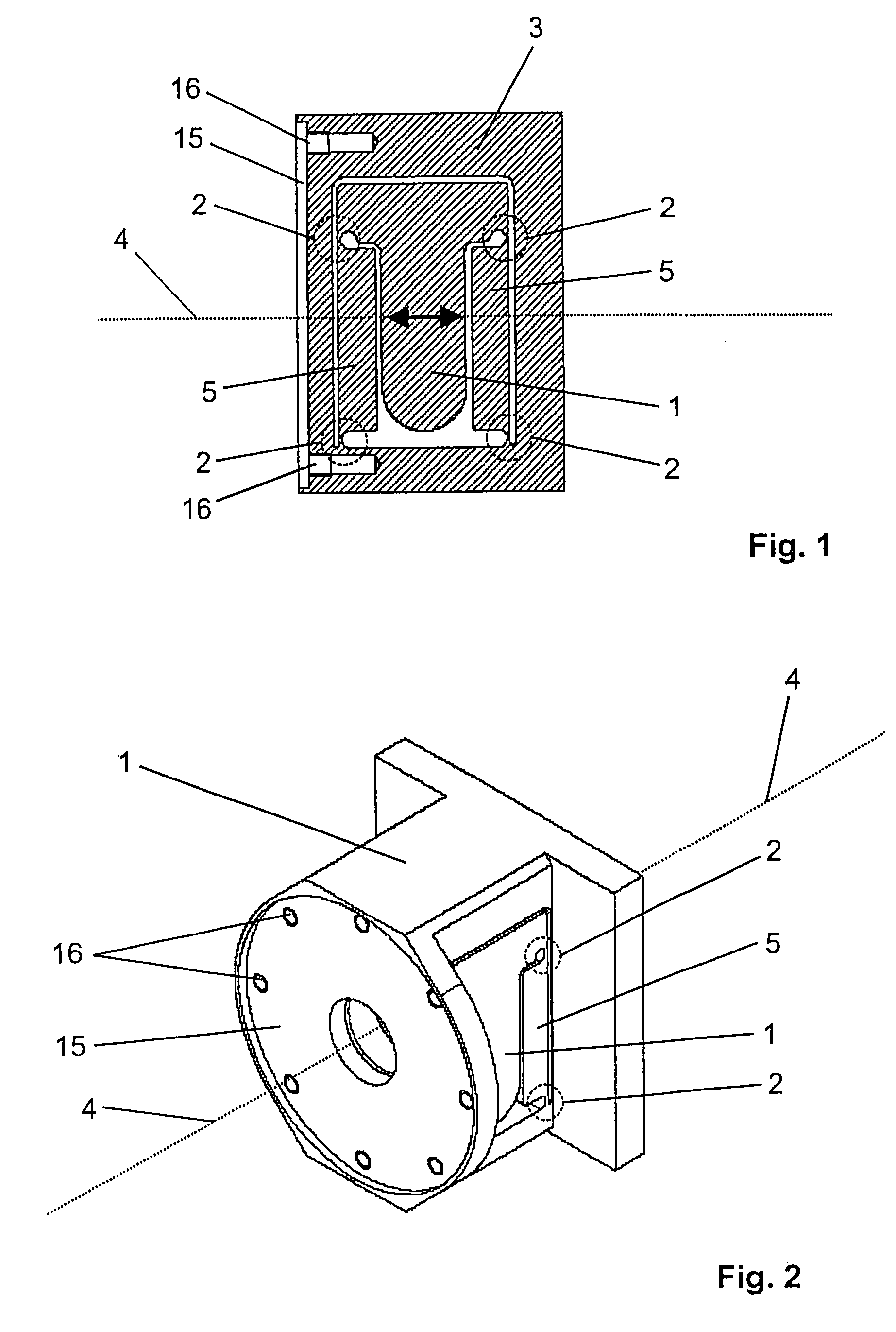
[0025]Turning now in detail to the drawings, FIGS. 1 and 2 show the element of a fiber coupler according to an embodiment of the invention that is provided for holding the focusing lens (not shown). The focusing lens is fixed in place in a pre-adjusted position on a lens holder 1.

[0026]Lens holder 1 is connected with a base body 3 by way of a total of four elastic monolithic or solid joints 2. Lens holder 1 is adjustable in linear manner in the axial direction, namely parallel to the optical axis 4. For this purpose, monolithic joints 2 have a clearly greater bending stiffness crosswise to optical axis 4 than parallel to it. In order to allow an essentially purely linear movement of the focusing lens, lens holder 1 is connected with base body 3 by way of the four monolithic joints 2 and two lever arms 5. In this connection, the two lever arms 5 are disposed in the manner of a parallelogram. This arrangement results in linear adjustability of the focusing lens, as indicated in FIG. 1...


PUM


Abstract

A fiber coupler for coupling light into an optical fiber and / or coupling light out of the fiber, has two holder elements, namely a fiber holder for holding the fiber, and a lens holder for holding a focusing lens. The holder elements are adjustable in the axial and transversal direction, respectively. In order to make such a fiber coupler available, which allows precise adjustment of the position of the focusing lens relative to the fiber, and which is furthermore compact in structure and inexpensive to produce, the holder elements are connected with a base body by way of at least one elastic monolithic joint, in each instance.

Description

CROSS REFERENCE TO RELATED APPLICATIONS[0001]Applicant claims priority under 35 U.S.C. §119 of European Application No. 04 028 837.5 filed Dec. 6, 2004.BACKGROUND OF THE INVENTION[0002]1. Field of the Invention[0003]The present invention relates to a fiber coupler for coupling light into an optical fiber and / or coupling light out of the fiber. The fiber coupler has two holder elements, namely a fiber holder for holding the fiber, and a lens holder for holding a focusing lens, whereby the holder elements are adjustable in the axial and transversal direction, respectively. Such fiber couplers are needed, among other things, in the sector of research, for optical experiments, and in the field of telecommunications technology, for systems for optical signal transmission.[0004]2. The Prior Art[0005]High requirements with regard to the precision of the positioning of the fiber end relative to the focusing lens are set for fiber couplers for coupling a free light beam into an optical fiber...

Claims


Application Information

Patent Timeline
Patent Type & Authority Patents(United States)
IPC IPC(8): G02B6/42G02B6/36
CPCG02B6/4226
Inventor HEIDEMANN, RAINER
Owner TOPTICA PHOTONICS AG
Why Eureka
Try Eureka