Evaporated fuel treatment apparatus

a technology of evaporation fuel and treatment apparatus, which is applied in the direction of combustion air/fuel air treatment, machine/engine, separation process, etc., can solve the problems of increasing manufacturing cost, complex structure, and correspondingly complicated structure, and achieve satisfactory adsorption/desorption performance, reduce manufacturing cost, and reduce the effect of refilling tim

Inactive Publication Date: 2002-09-12
HONDA MOTOR CO LTD
View PDF1 Cites 41 Cited by
  • Summary
  • Abstract
  • Description
  • Claims
  • Application Information

AI Technical Summary

Benefits of technology

0009] The present invention has been made to solve the foregoing problems, and it is an object of the invention to provide an evaporated fuel treatment apparatus which is capable of

Problems solved by technology

The conventional evaporated fuel treatment apparatus requires the discharge control electromagnetic valve, fuel supply discharge passage, switch and the like provided for reducing the refilling time, thereby resulting in a correspondingly complicate

Method used


Image

  • Evaporated fuel treatment apparatus
  • Evaporated fuel treatment apparatus
  • Evaporated fuel treatment apparatus

Examples


Embodiment Construction

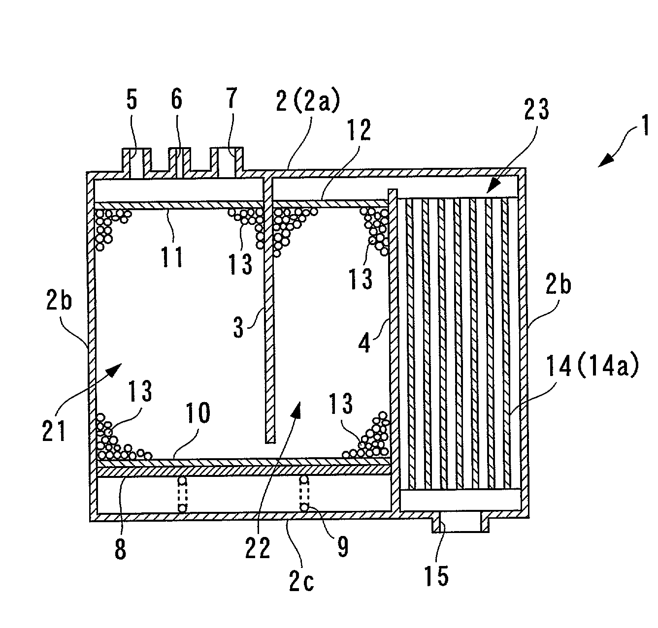
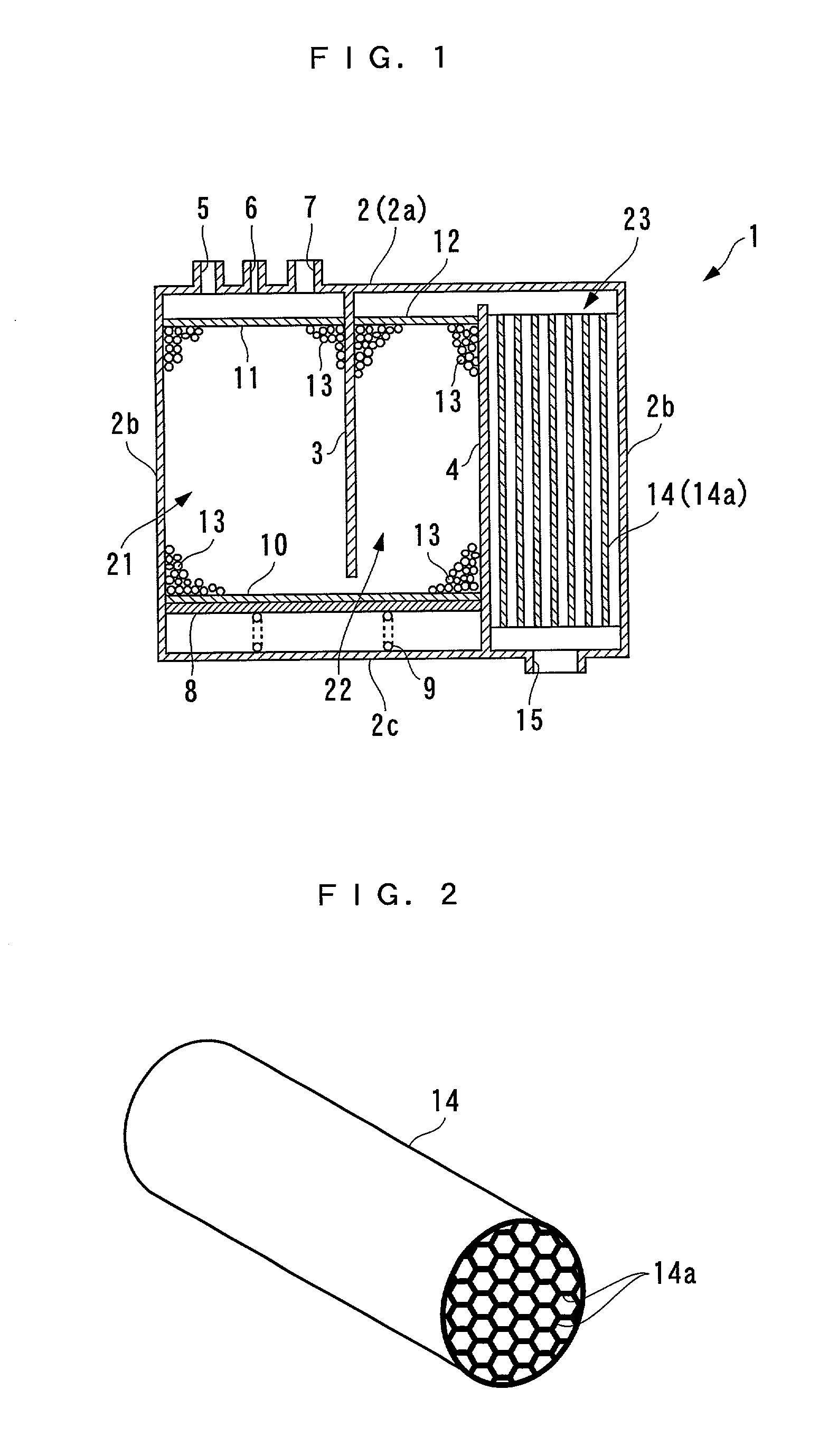
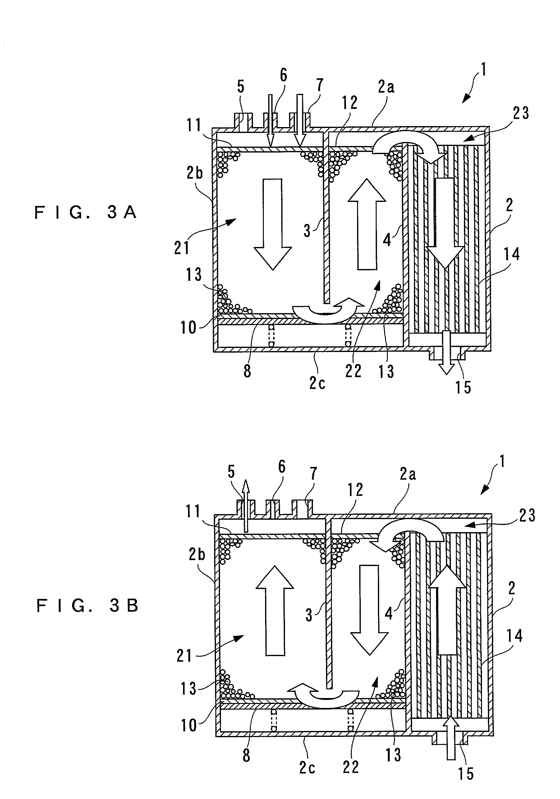
[0027] In the following, one embodiment of the present invention will be described in detail with reference to the accompanying drawings. FIG. 1 generally illustrates the structure of an evaporated fuel treatment apparatus according to the embodiment. As illustrated, the evaporated fuel treatment apparatus (hereinafter called the "canister") 1 comprises a casing 2 formed of a top wall 2a, four side walls 2b and a bottom wall 2c; a first chamber 21 (main chamber), a second chamber 22 (main chamber), and a third chamber 23 (sub-chamber) defined by partitioning the casing 2 by two partition walls 3, 4; and the like.

[0028] The top wall 2a of the first chamber 21 is provided with a purge port 5, a charge port 6, and a fuel supply charge port 7. A purge passage, in communication with an intake pipe of an engine (either of them is not shown in the figure), is connected to the purge port 5. A purge control valve, not shown, is disposed midway in the purge passage. The opening of the purge c...


PUM

PropertyMeasurementUnit
Shapeaaaaaaaaaa

Abstract

An evaporated fuel treatment apparatus is provided for reducing a refilling time, ensuring satisfactory adsorption/desorption performance for an evaporated fuel, and reducing the manufacturing cost through a simplified structure. The evaporated fuel treatment apparatus comprises a casing having formed therein a first chamber in communication with the fuel tank, a second chamber in communication with the first chamber, and a third chamber in communication with the second chamber and the atmosphere. Active carbons are contained in the first chamber and second chamber for adsorbing fuel components in an evaporated fuel introduced from the fuel tank. An adsorbent is contained in the third sub-chamber for adsorbing fuel components in the evaporated fuel introduced from the second chamber. The adsorbent has an air-flow resistance which is set smaller than that of the active carbons.

Description

[0001] 1. Field of the Invention[0002] The present invention relates to an evaporated fuel treatment apparatus which temporarily adsorbs fuel components within an evaporated fuel to conveniently discharge the evaporated fuel to an intake passage in order to prevent the emission to the atmosphere of the evaporated fuel generated in a fuel tank of an internal combustion engine.[0003] 2. Description of the Prior Art[0004] Conventionally, the evaporated fuel treatment apparatus of the type mentioned above is generally called a canister, and is known, for example, from Laid-open Japanese Patent Application No. Hei 7-332171. This canister comprises a box-shaped casing; three chambers, a first through a third chamber defined by partitioning the casing by partition walls; and active carbons filled in each chamber. The first and second chambers, and the second and third chambers communicate with each other. The first chamber is connected to an intake pipe through a purge passage, and is also...

Claims


Application Information

Patent Timeline
IPC IPC(8): B01D53/04F02M25/08
CPCB01D53/0415B01D53/0446B01D2253/102B01D2253/304B01D2253/3425B01D2257/702B01D2258/01B01D2259/40081B01D2259/40086B01D2259/4516B01D2259/4566F02M25/0854
Inventor HARA, TAKESHIMIHARA, HIROAKI
Owner HONDA MOTOR CO LTD
Why Eureka
Try Eureka