Image pick-up apparatus

a technology of image pickup and output image, which is applied in the direction of instruments, television systems, color signal processing circuits, etc., can solve the problems of block borders appearing in the output image, affecting the quality of the output image, so as to prevent the degradation of the output image image quality

Inactive Publication Date: 2002-09-12
SHARP KK
View PDF0 Cites 49 Cited by
  • Summary
  • Abstract
  • Description
  • Claims
  • Application Information

AI Technical Summary

Benefits of technology

[0027] The first objective of the present invention is to provide an image pick-up apparatus which, even in the case when there is a light-quantity difference between two original images or in the case when portions of the images have different light quantities, can prevent degradation of the image quality of an output image by properly correcting the light-quantity difference.
[0028] In order to achieve the above-mentioned objective, the image pick-up apparatus of the present invention is provided with: an image pick-up section for picking up imaging light from a subject and forming image data; an image-shift mechanism for shifting the image pick-up section to a plurality of relative positions with respect to the imaging light so as to allow the image pick-up section to form the image data at the relative positions; an LPF, constituted by a filter, for eliminating a spatial frequency component that is generated due to a light-quantity difference between a plurality of pieces of image data that the image pick-up section has formed by using the image-shift mechanism; and a memory control section for combining the plurality of the image data.
[0029] In the above-mentioned image pick-up apparatus, the LPF, which serves as a filter for correcting light-quantity differences occurring between a plurality of original image signals that have been generated by an image-shift operation made by the image-shift mechanism, is installed; therefore, it is possible to suppress striped patterns occurring due to the light-quantity differences, and consequently to improve the image quality.
[0030] Moreover, after combining the plurality of the original images, the filtering by the LPF is carried out prior to an interpolating process; thus, it becomes possible to reduce the amount of processes concerning the light-quantity correction (filtering), and consequently to allow high-speed processing.
[0031] Furthermore, by carrying out the filtering of the LPF after the interpolating process of the combined image, it becomes possible to suppress striped patterns occurring due to the interpolating process simultaneously with the suppression of the striped patterns occurring due to the light-quantity differences, and consequently to improve the image quality. It also becomes possible to correct edges in the horizontal or vertical direction accurately.

Problems solved by technology

However, even in the case of equal exposing time, a difference in light quantity may occur between the two original images due to flickers of a fluorescent lamp or other reasons.
If there is a difference in light quantity between the two sheets of original images, a diced pattern, which is originally not supposed to appear in the imaging light, tends to appear in the output image, resulting in degradation in the image quality. FIG. 33 shows an example of the diced pattern that appears even when an image of a flat blank pattern is picked up.
However, the problem with light-quantity-difference correction method (I) is that block borders tend to appear in the output image (similar to the known block distortion appearing in image-compressing techniques) since the light-quantity-difference correction is carried out for each block.
Moreover, since the light-quantity-difference correction is carried out based on the three light quantities, that is, the minimum value, the average value and the maximum value, errors in these three parameters tend to give serious adverse effects.
Moreover, the problem with light-quantity-difference correction method (II) is that false edges tend to appear at edge portions, causing double edges or an insufficient light-quantity-difference correction in the periphery of edges.
For this reason, if the light-quantity difference varies depending on regions, such as a light-axis portion and peripheral portions, of the original image, it is not possible to carry out the light-quantity-difference correction properly.
In particular, in the case when exposing time is controlled by a mechanical shutter, the exposing time for the vicinity of the light axis becomes longer than that for the peripheral portions, thereby causing degradation in the image quality.

Method used


Image

  • Image pick-up apparatus
  • Image pick-up apparatus
  • Image pick-up apparatus

Examples


embodiment 1

[Embodiment 1]

[0069] The following description will discuss one embodiment of the present invention.

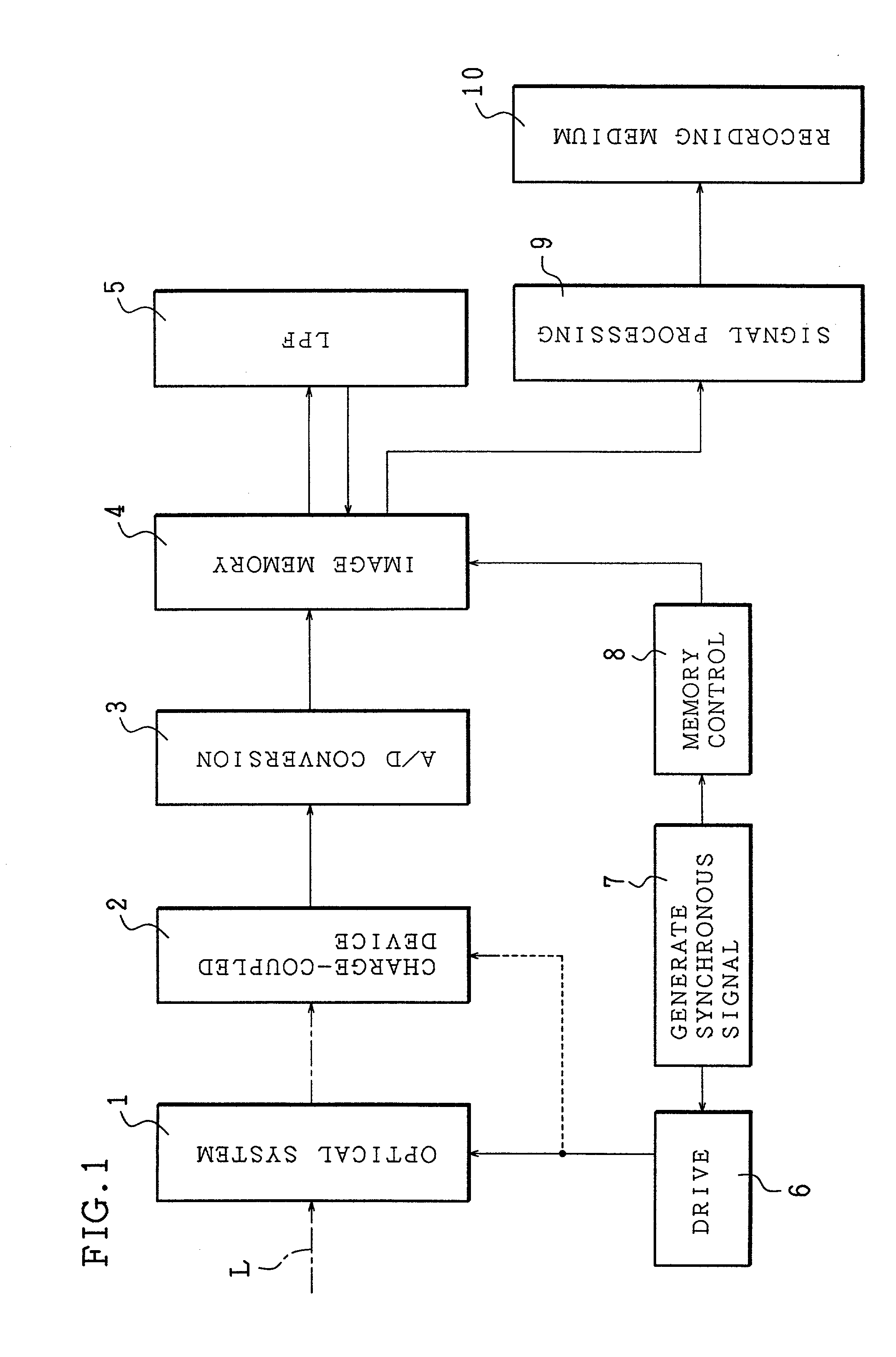
[0070] As illustrated in FIG. 1, an image pick-up apparatus of the present embodiment is provided with an optical system 1, a charge-coupled device 2, an A / D converter (an Analog to Digital Converter) 3, an image memory 4, an LPF 5, a driving section 6, a synchronous-signal generating section 7, a memory control section 8, a signal-processing section 9 and a recording medium 10.

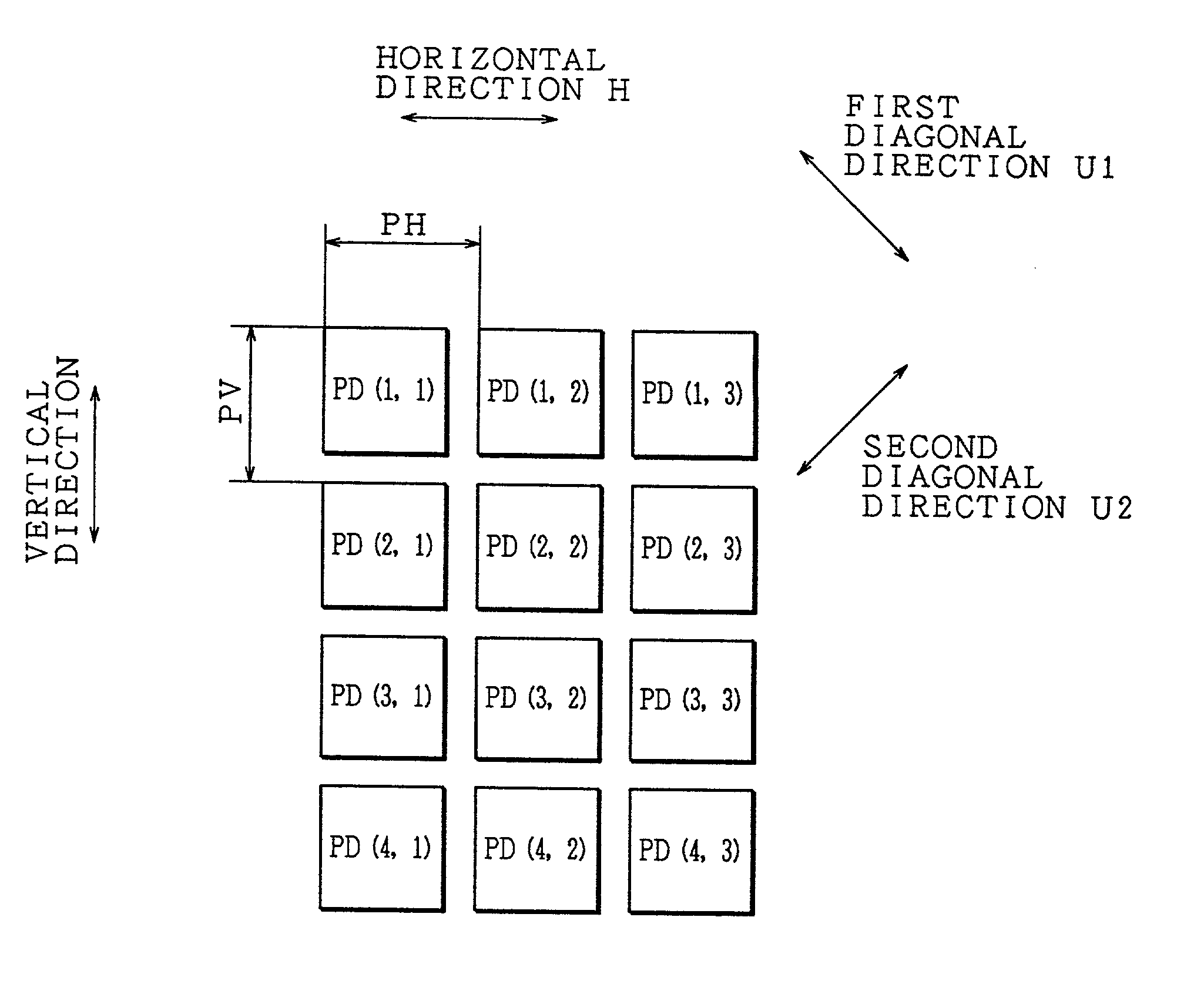
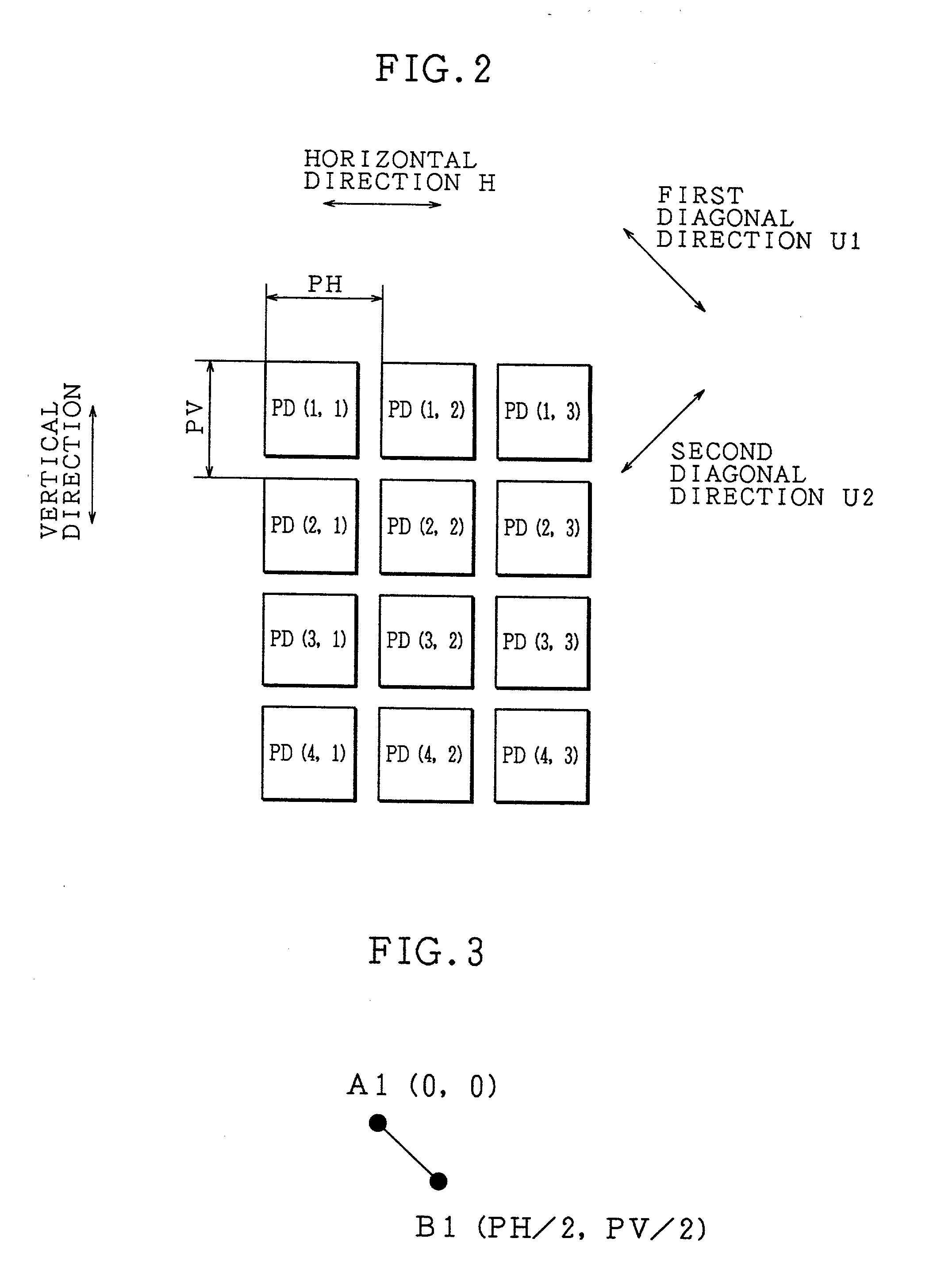
[0071] Imaging light from a subject is converged by a light-converging lens of the optical system 1, and then focused onto the image-forming surface of the charge-coupled device 2. A plurality of light-receiving regions PD are arranged in the matrix format on the image-forming surface of the charge-coupled device 2.

[0072] Besides the light-converging lens for converging imaging light, the optical system 1 has an image-shift mechanism. The image-shift mechanism is driven by the driving section 6 so that it allow...

embodiment 2

[Embodiment 2]

[0114] The following description will discuss another embodiment of the present invention. Here, the image pick-up apparatus of the present embodiment has a similar construction to the image pick-up apparatus of Embodiment 1; therefore, for convenience of explanation, those members that have the same functions and that are described in Embodiment 1 are indicated by the same reference numerals and the description thereof is omitted.

[0115] Different from the aforementioned Embodiment 1, the image pick-up apparatus of the present embodiment carries out the image shift in the horizontal direction H.

[0116] FIG. 6 is a drawing that indicates a positional relationship between the first and second image-forming positions with respect to imaging light. Based on the first image-forming position A2, the second image-forming position B2 is shifted from the first image-forming position A2 by half the length of the array period PH (PH / 2) in the horizontal direction H of the light-re...

embodiment 3

[Embodiment 3]

[0145] The following description will discuss another embodiment of the present invention. Here, the image pick-up apparatus of the present embodiment has a similar construction to the image pick-up apparatuses of Embodiments 1 and 2; therefore, for convenience of explanation, those members that have the same functions and that are described in Embodiments 1 and 2 are indicated by the same reference numerals and the description thereof is omitted.

[0146] Different from the aforementioned Embodiments 1 and 2, the image pick-up apparatus of the present embodiment carries out the image shift in the vertical direction V.

[0147] FIG. 9 is a drawing that indicates a positional relationship between the first and second image-forming positions with respect to imaging light. Based on the first image-forming position A3, the second image-forming position B3 is shifted from the first image-forming position A3 by half the length of the array period PV in the vertical direction V of ...


PUM


Abstract

An image pick-up apparatus is provided with: a charge-coupled device for picking up imaging light from a subject and forming image data; an image-shift mechanism for shifting the charge-coupled device to a plurality of relative positions with respect to the imaging light so as to allow the charge-coupled device to form the image data at the relative positions; an LPF constituted by a filter for removing a spatial frequency component that appears due to a light-quantity difference between a plurality of pieces of image data generated by the charge-coupled device through the image-shift mechanism; and a memory control section for combining the plurality of image data. With this arrangement, it is possible to suppress a striped pattern due to the light-quantity difference, and consequently to improve the image quality.

Description

FIELD OF THE INVENTION[0001] The present invention relates to an image pick-up apparatus that is capable of providing images with high resolution, and more particularly, concerns an image pick-up apparatus which picks up a plurality of images by relatively shifting imaging light from a subject, and combines these images into an image with an enhanced resolution.BACKGROUND OF THE INVENTION[0002] Recently, still-image pick-up apparatuses, so-called electronic still cameras, have been put into practical use as image pick-up apparatuses for picking up still images. Further, home-use video cameras have been put into practical use as motion-image pick-up apparatuses for picking up motion images. In these image pick-up apparatuses, a charge-coupled device is used as a means for picking up an image by receiving imaging light from a subject.[0003] The charge-coupled device is a so-called two-dimensional CCD image sensor. In the charge-coupled device, a plurality of light-receiving regions ar...

Claims


Application Information

Patent Timeline
Patent Type & Authority Applications(United States)
IPC IPC(8): H04N5/20H04N5/21H04N9/04H04N5/225H04N9/07H04N9/64
CPCH04N5/20H04N5/21H04N9/045H04N9/646H04N5/349H04N25/48H04N23/843H04N25/134
Inventor YAMADA, EIJIHARADA, TOSHIAKIIWAKI, TETSUO
Owner SHARP KK
Why Eureka
Try Eureka