Cable storage cartridge

a technology of cable storage and cable spool, which is applied in the direction of optics, fibre mechanical structures, instruments, etc., can solve the problems of inconvenient use of fiber optic patch cords terminating at attached connectors, spools that cannot accommodate a wide variety of excess cable lengths, and prior art apparatus, etc., to achieve the effect of increasing cable storage density

Inactive Publication Date: 2002-09-12
COMMSCOPE TECH LLC
View PDF0 Cites 56 Cited by
  • Summary
  • Abstract
  • Description
  • Claims
  • Application Information

AI Technical Summary

Benefits of technology

0009] One aspect of the present invention relates to a cable storage cartridge having a carriage frame and first and second spool members. The spool members cooperate to form a spool which rotates within the carriage frame. The first spool member includes a loop channel for removably fixing a loop end of the cable to be stored to the spool. The spool members are configured with a center post around which the cable is wrapped for storage. A storage chamber defined by the spool members and the carriage frame lies in a plane spaced from the plane occupied by the loop channel of the first spool member allowing for increased cable storage density. The cable passes from the loop channels to the storage chamber by means of transition holes defined by the first spool member.

Problems solved by technology

One disadvantage of the prior art apparatus is illustrated in the aforesaid U.S. Pat. No. 4,792,203.
Accordingly, the spool does not accommodate a wide variety of excess cable lengths.
Also, and perhaps more importantly, U.S. Pat. No. 4,798,432 is not conveniently used with fiber optic patch cords terminating at attached connectors.
In the aforesaid patent, the hole through which the fiber is to be fed is too small to accommodate a connector.
Furthermore, in U.S. Pat. No. 5,013,121, the amount of storage capacity is limited by the fact that the cable is wound around the outside of the radius limiting configuration on top of the spool.

Method used


Image

  • Cable storage cartridge
  • Cable storage cartridge
  • Cable storage cartridge

Examples


Embodiment Construction

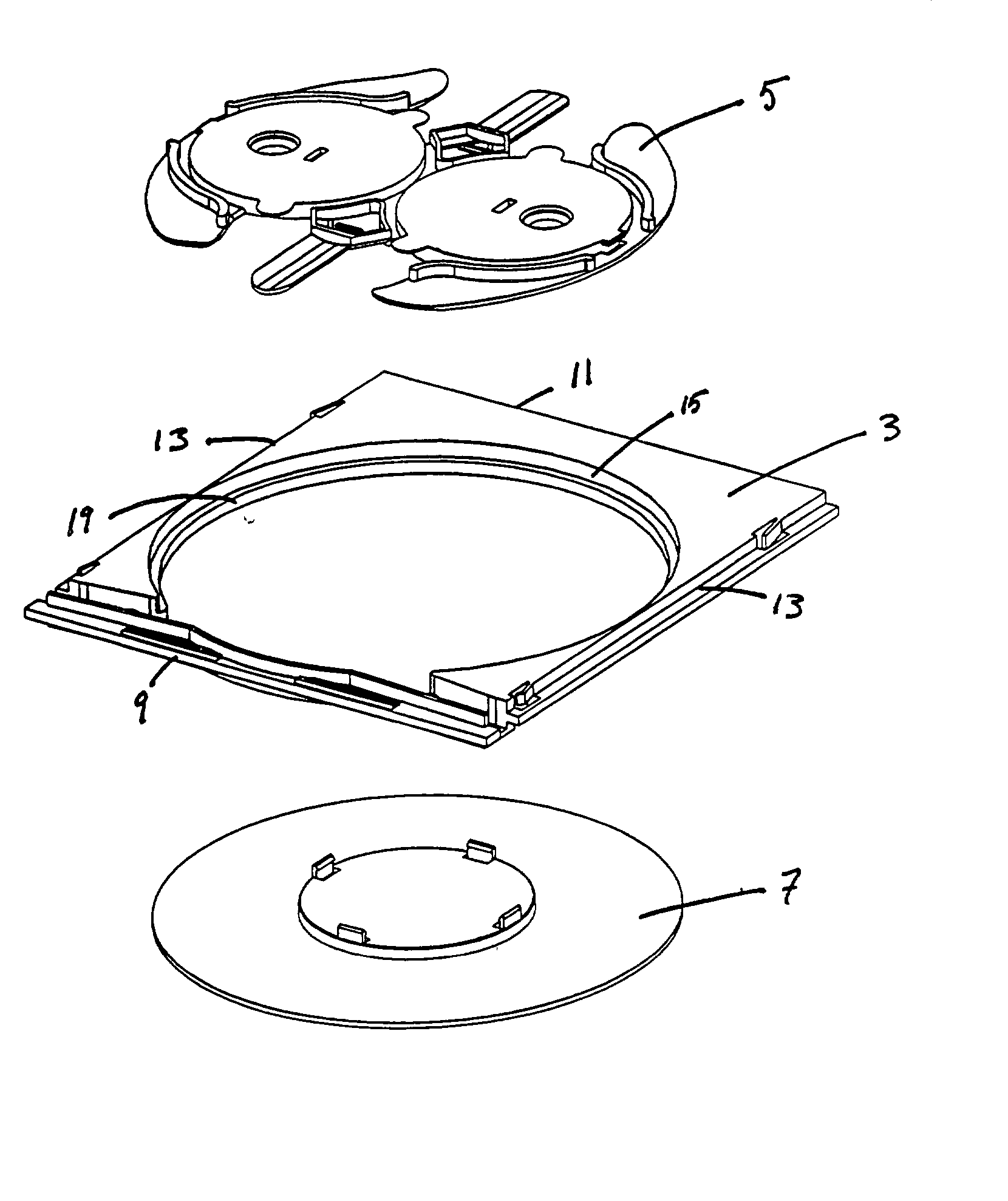
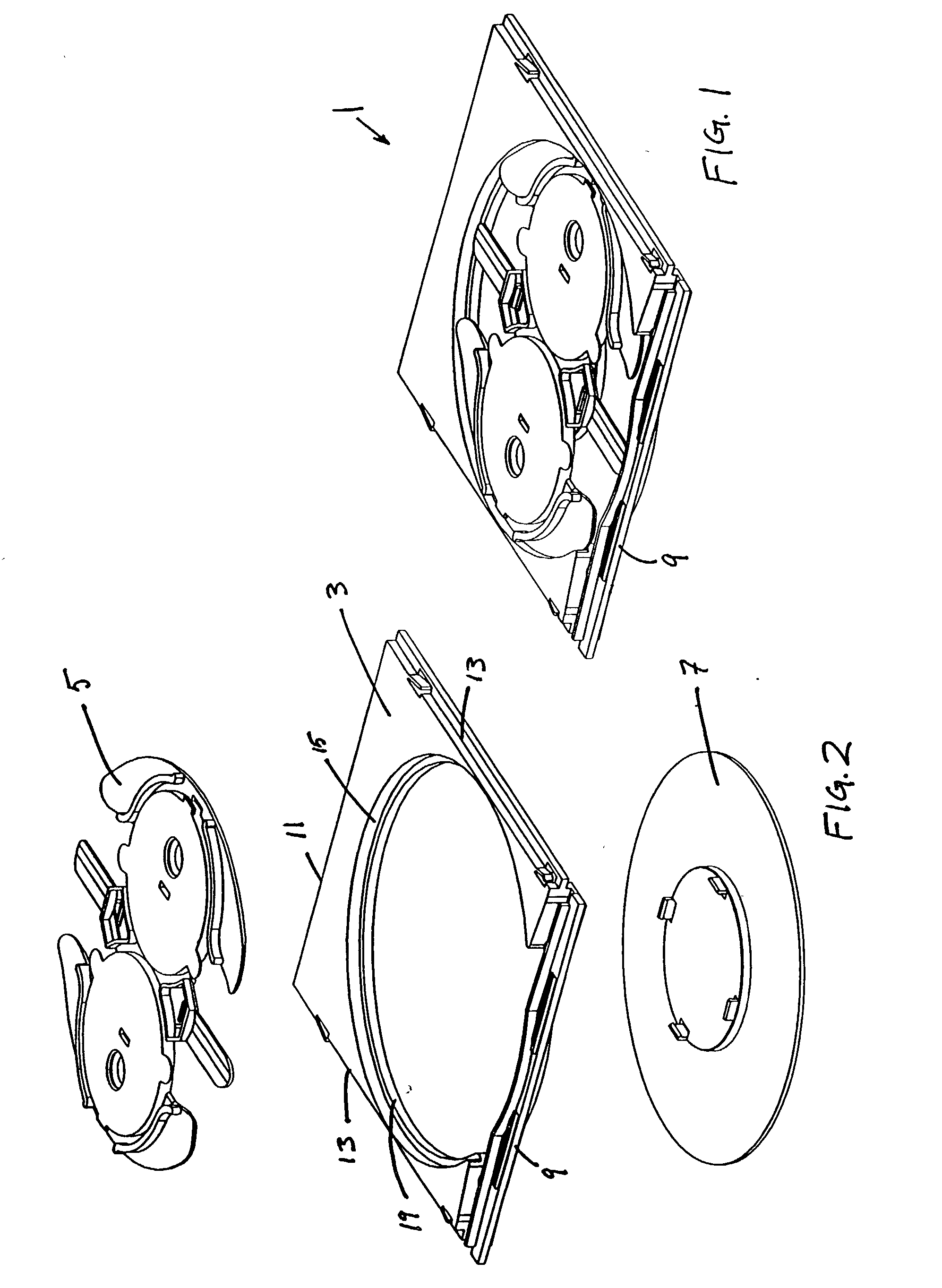
[0034] Referring now to the several drawing figures in which identical elements are numbered identically throughout, a cable storage cartridge 1 according to the present invention is shown. A shown in FIGS. 1 and 2 the cartridge 1 includes a carriage frame 3, an upper spool member 5 and a lower spool member 7. Although the terms upper and lower will be used for convenience throughout this specification, it is to be understood that the orientation of the spool members is not critical to the invention, and, therefore, the invention may include first and second spool members where either spool member may be oriented as the upper spool member or may even be oriented in a non-vertical alignment such as horizontally or at some angle between vertical and horizontal.

[0035] The upper spool member 5 and the lower spool member 7 combine to form a spool. The spool members 5 and 7 are rotatably received by the carriage frame 3 so that the spool formed by the spool members 5 and 7 may freely rota...


PUM


Abstract

A cable storage cartridge and assembly for storing an excess length of cable. The cartridge includes a rectangular carriage frame and a spool rotatably disposed inside the carriage frame. The spool is comprised of a first spool member having a radius protection loop channel on its top surface and a second spool member. Together the first spool member and second spool member define a storage chamber. The storage chamber lies in a different plane than the loop channel of the first spool member. The first spool member defines transition openings for allowing the cable to pass from the loop channel to the storage chamber. Carriage frame includes detent and catch tabs for retaining the cartridge inside a cartridge housing.

Description

[0001] This invention pertains to a communication system in which signals are carried through cables or optical fibers. More particularly, this invention pertains to a storage container for taking up and storing excess amounts of cable or fiber.BACKGROUND OF THE INVENTION[0002] The telecommunications industry is rapidly proceeding with the development and installation of optical fiber transmission systems. An optical fiber networks and other cable networks require numerous techniques for managing and connecting a large number of cables.[0003] In the management of cables and optical fibers, it is necessary from time to time to provide slack or excess amounts of cable lengths. In order that cable network systems are neatly arranged and manageable, the excess amounts must be stored in a neat and orderly manner for facilitating ease of use of the network apparatus.[0004] Devices for storing excess amounts of optical fiber cables are known in the art. For example, commonly assigned U.S. ...

Claims


Application Information

Patent Timeline
Patent Type & Authority Applications(United States)
IPC IPC(8): G02B6/44
CPCG02B6/4452G02B6/4453G02B6/4457
Inventor HOLMAN, JOHN C.SMITH, TREVOR D.TINUCCI, THOMAS C.
Owner COMMSCOPE TECH LLC
Why Eureka
Try Eureka