Method for photographing lustrous objects, method for photographing spectacle frames, and method for creating electronic spectacle frame catalogue

a technology for photographing spectacles and objects, applied in the field of photographing spectacle frames, can solve problems such as difficulty in obtaining good images, and achieve the effect of facilitating subsequent editing and handling

Inactive Publication Date: 2002-09-12
SAIGO TSUYOSHI
View PDF0 Cites 4 Cited by
  • Summary
  • Abstract
  • Description
  • Claims
  • Application Information

AI Technical Summary

Benefits of technology

0017] Use of a digital camera in photography enables digital information about spectacle frame images to be obtained, thus making subsequent editing and handling much simpler.

Problems solved by technology

However, it is still difficult to obtain a good image even when an spectacle frame is placed in a dark box and photographed under indirect light.
In particular, when there is much surface lustre on the spectacle frame, such as with a metal frame, the camera or background mages are reflected on the surface of the spectacle frame and the natural hues cannot be photographed.

Method used


Image

  • Method for photographing lustrous objects, method for photographing spectacle frames, and method for creating electronic spectacle frame catalogue
  • Method for photographing lustrous objects, method for photographing spectacle frames, and method for creating electronic spectacle frame catalogue
  • Method for photographing lustrous objects, method for photographing spectacle frames, and method for creating electronic spectacle frame catalogue

Examples


embodiment 1

[0033] (Embodiment 1)

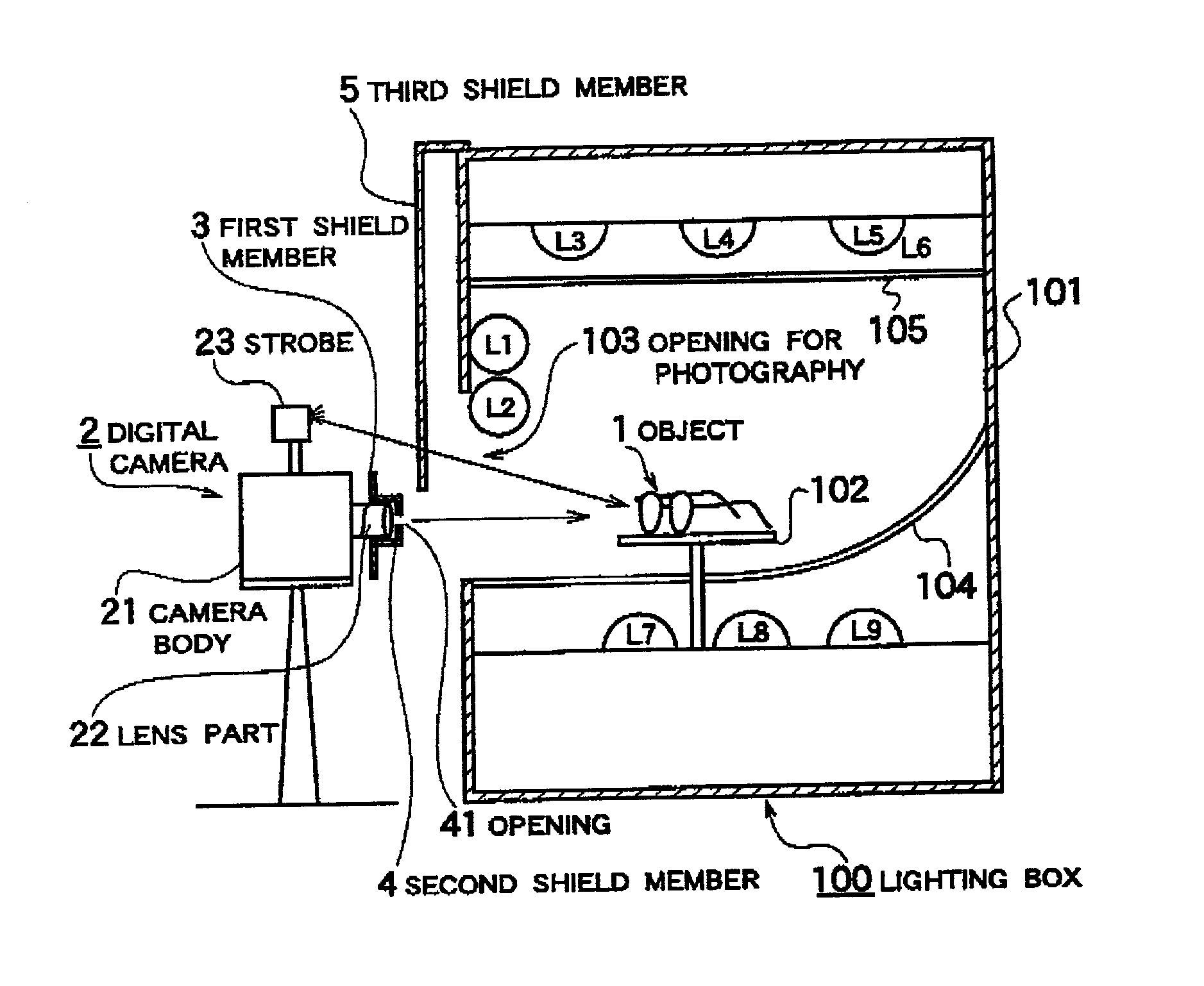
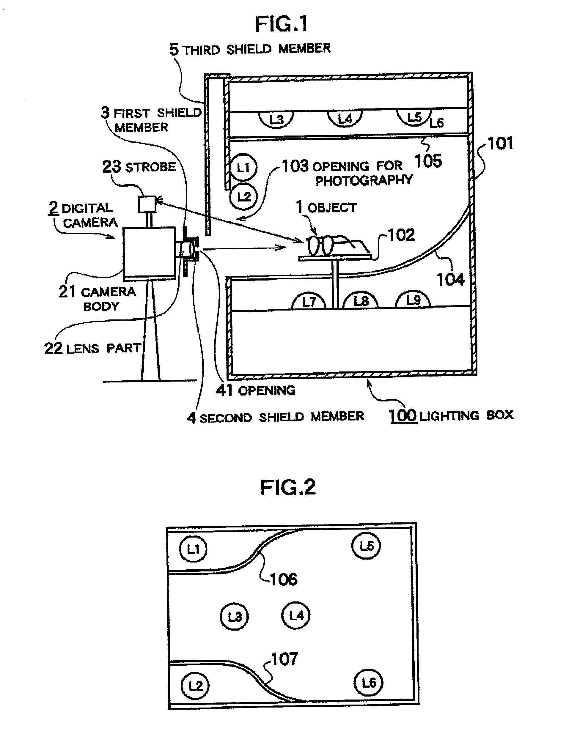
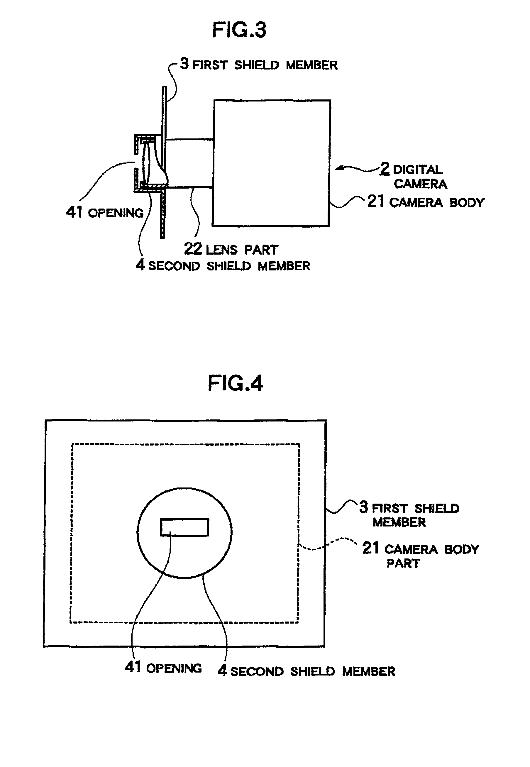
[0034] Hereinbelow, the method for photographing spectacle frames used in the embodiments of the present invention will be explained using the diagrams for reference. FIG. 1 is a partial cross-section showing an overview of the configuration of the device for implementing the method for photographing spectacle frames in a first embodiment of the present invention. FIG. 2 is a cross-section through the top of a lighting box, FIG. 3 is a partially cut-away view through part of the shield member mounted onto the digital camera, and FIG. 4 is a front view of the shield member.

[0035] As shown in FIG. 1, this method is a method for photographing an object 1 using a digital camera 2. The object 1 is a highly lustrous metal spectacle frame. In this example, the object 1 is set in a lighting box 100. The digital camera 2 has a lens of a diameter that is relatively large compared to that of an ordinary single-lens reflex camera. The lens part 22 at the front of the camera...

embodiment 2

[0058] (Embodiment 2)

[0059] FIGS. 11 and 12 are diagrams for explaining the photographic lighting box in the method for photographing spectacle frames in a second embodiment of the present invention. FIG. 11 is an external perspective view of a photographic lighting box and FIG. 12 is an enlarged partial cross-section of the interior configuration of the photographic lighting box. FIGS. 13 and 14 show the arrangement of lighting lamps within the photographic lighting box.

[0060] The photographic lighting box 200 in these figures incorporates various devices in a white plastic main case 201. At approximately the centre of the panel on the front of this main case 201 is an opening for photography 201a. Below this opening for photography 201a is a camera stand 201b. A digital camera 221 is placed on this camera stand 201b and this camera 221 is used for the photography. On the rear panel 201c is a door that can be open and shut and that can be used to place the object, that is the spect...


PUM


Abstract

The present invention provides a method for photographing lustrous objects, including even spectacle frames with highly reflective surfaces such as metal frames, that enables the objects to be photographed more naturally and aesthetically without any reflection on the surface of the camera or lens. The present invention also provides a method for photographing spectacle frames and a method for creating an electronic spectacle frame catalogue using this method. The method is one in which the camera 2 photographs the lustrous object 1. Optical shield members 3, 4, and 5 are placed between the camera body 21 and the lens 22 of the camera 2, and the lustrous object 1 so that a reflection of said camera 2 is not be formed on the photographed image of the lustrous object. In addition, an opening 41, having a size and shape suitable for photographing an image of the lustrous object 1, is provided in the shield member 4 of the lens 22.

Description

TECHNICAL FIELD[0001] The present invention relates to a method for photographing lustrous objects such as metal spectacle frames, for example, and to a method for photographing spectacle frames.BACKGROUND ART[0002] When creating catalogues or pamphlets for spectacle frames, or when simulating the wearing of spectacle frames, images of the spectacle frames must be photographed. For example, in the spectacle frame try-on simulation device described in Japanese Patent Application Laid-open No. 61-80222 or in Japanese Patent Application Laid-open No. 63-76581, an image of an spectacle frame is photographed with a video camera and simulation occurs by synthesizing this image with an image of a person that has been photographed separately. Furthermore, Japanese Patent Application Laid-open No. 63-172220 describes a method wherein the R, G, and B values of each dot in a static image of an spectacle frame loaded onto a computer by a video camera are scanned and the spectacle frame data and...

Claims


Application Information

Patent Timeline
Patent Type & Authority Applications(United States)
IPC IPC(8): G02C13/00G03B15/06
CPCG02C13/003G03B15/06
Inventor SAIGO, TSUYOSHITAMURA, NORIAKI
Owner SAIGO TSUYOSHI
Why Eureka
Try Eureka