
Wall panel system

a wall panel and system technology, applied in the field of wall panel systems, can solve the problems of requiring excessive time and manpower, complex addition or removal of stackable upper wall panels, and requiring excessive amounts of time and manpower to effect the necessary or desired change, and achieves the effect of easy and quick reconfiguration, installation or removal quickly and easily, and minimal effor

Inactive Publication Date: 2002-09-19
MILLERKNOLL INC
View PDF0 Cites 40 Cited by
  • Summary
  • Abstract
  • Description
  • Claims
  • Application Information

AI Technical Summary

Benefits of technology

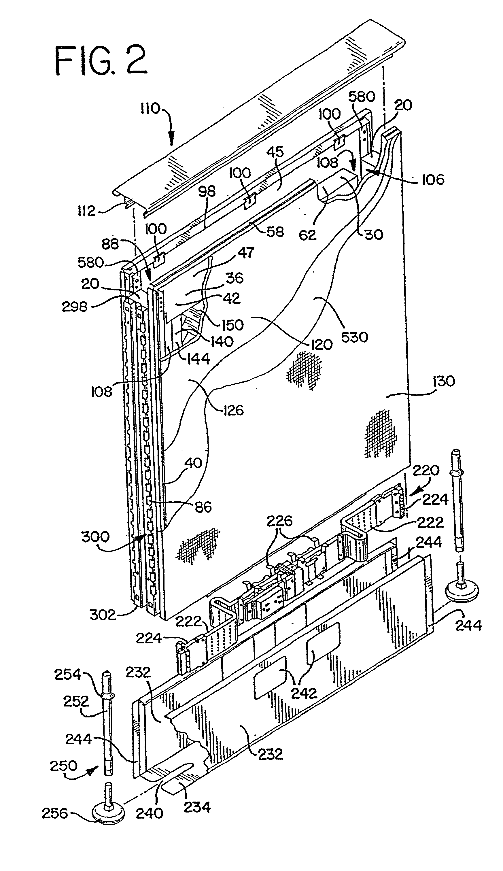
[0020] In one embodiment, the corner post is provided with a height adjustable cap which includes a post member and a cover member supported by the post member. The post member threadably engages the hole in the upper plate and can be rotated to adjust the height of the cover. In this way, the cover can be raised or lowered to provide a smooth transition between adjacent wall panel top caps.
[0048] Finally, the wall panel construction lends itself to improved manufacturability and overall quality. Most importantly, as described above, each frame member can be made with extremely tight tolerances so that the gap between panels is maintained as a constant when the wall panels are assembled as a system. Or, in an alternative embodiment, the wall members can be centered on the core assembly so as to maintain similar uniform gaps. By locating the frame members to outside dimensions in the fixture, the overall panel construction is improved by providing extremely tight tolerances for the height and width of each panel. The improved quality associated with this method of manufacture in turn facilitates and eases installation of the panels while providing an improved overall look for the system.

Problems solved by technology

Often, however, the addition or removal of stackable upper wall panels can involve complex, multiple parts and require excessive amounts of time and manpower to effect the necessary or desired change.

Method used


Image

  • Wall panel system
  • Wall panel system
  • Wall panel system

Examples


second embodiment

[0302] In a preferred embodiment, the strip 160 also includes a second hook member 166. In one embodiment, shown in FIG. 23, the second hook member 166 is positioned opposite of the first hook 164 and faces the same direction as the first hook member, i.e., opens inwardly away from the folded edge 133 of the fabric when it is folded over on itself. In a second embodiment, shown in FIG. 22, the second hook 168 is positioned at the end of the strip and opens outwardly away from the outer surface 136 of the fabric. In either embodiment, the second hook member 166, 168 is adapted to allow an installer to stretch tightly the fabric 130 while installing the first hook 164 on the outer leg 118 of the sidewall member.

[0303] To facilitate the installation of the fabric 130, a tool 170 is provided. The tool 170 includes a mounting block 171, a blade 172, a handle 174 and a housing 176 as shown in FIGS. 46-47. The mounting block 171 is mounted to the housing and includes a lip portion 173 adap...

first embodiment

[0385] Now referring to FIG. 80, a pair of lower wall panels are shown as attached to a corner post as described above. As described above, the corner post 320, in combination with one or more pairs of draw rods 296 and upper and lower draw blocks 280, 290, function as a connector member to connect the lower wall panels. A corner post extension 1120, shown in FIGS. 85 and 86, is then mounted to the top of the corner post, and can also be considered as part of the connector member. In a first embodiment, the corner post extension has the same construction as the corner post described above (with the same reference numbers calling out those aspects that are the same), except that the lower plate member 326 is mounted distally from the lower end of the extension. In addition, each side of the extension has a cut out 1126 along the lower end of the extension below the lower plate member. A leg portion 1128, formed as an L-shaped angled member, is welded in each corner of the extension a...


PUM


Abstract

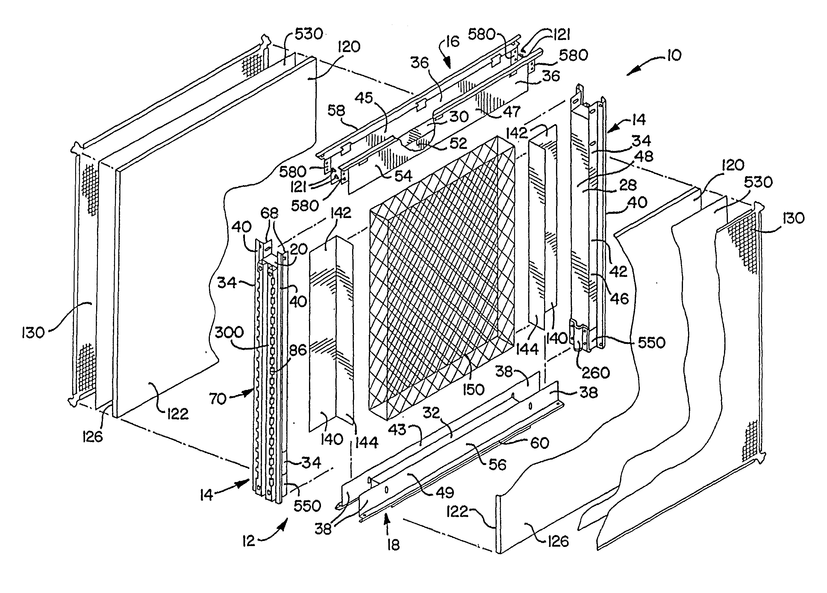
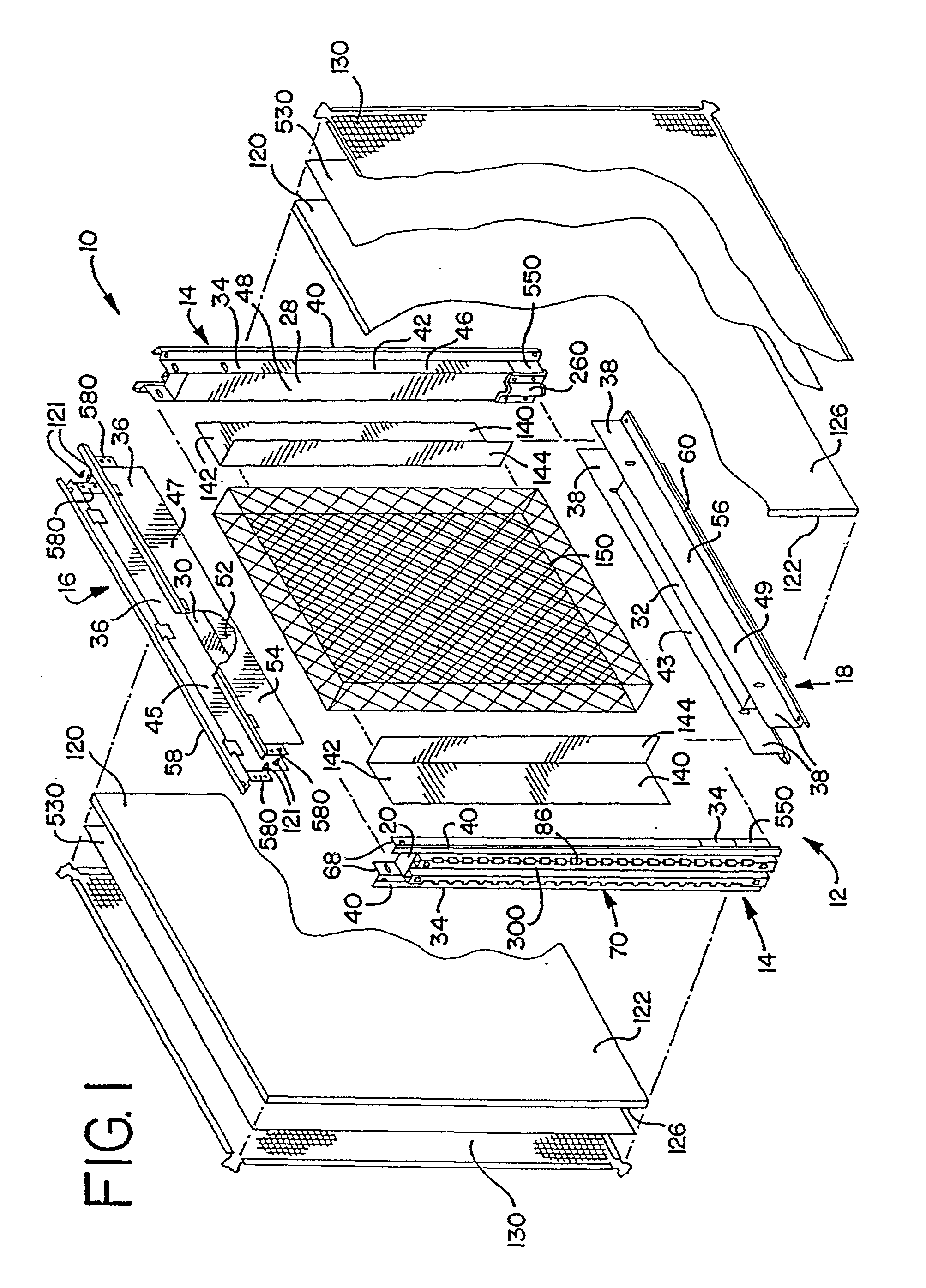
A stackable wall panel assembly including a lower wall panel having a top, a bottom, vertically extending ends and opposite sides and an upper wall panel having a top, a bottom, vertically extending ends and opposite sides. A vertically extending stanchion has a lower end connected to the top of the lower wall panel and an upper end connected to the bottom of the upper wall panel. The bottom of the upper wall panel is spaced from the top of the lower wall panel to form an open space between the upper and lower wall panels. In a preferred embodiment, a rail extends between the stanchions. Also in a preferred embodiment, a cover covers the space formed between the upper and lower wall panels. In another aspect, a second stanchion is connected to the top of the upper wall panel and a second upper wall panel is connected to the top of the second stanchion. In one preferred embodiment, draw members connect the first upper wall panel to the first stanchion and connect the second upper wall panel to the second stanchion. Alternatively, a draw block, insert and draw rod are used to connect the first upper wall panel to the lower wall panel, and to connect the first and second upper wall panels. In another aspect, a draw rod connects a lower connector post to a first upper connector post, with a spacer post disposed therebetween. A method for assembling a stackable wall panel assembly is also provided.

Description

[0001] This application claims the benefit of U.S. Provisional Application No. 60 / 267,867, filed Feb. 9, 2001, the entire disclosure of which is hereby incorporated herein by reference.BACKGROUND[0002] The present invention relates generally to a wall panel system, and in particular, to a stackable wall panel system.[0003] Panel systems are commonly used to divide large, open office space into separate work spaces. For example, Herman Miller, Inc., the assignee of the present application, manufacturers and sells three such work space management systems: the ACTION OFFICE.RTM. system, the ETHOSPACE.RTM. system and the Q.TM. System. Typically, workspace management systems are comprised of a series of wall panels arranged in various configurations. For example, wall panels can be connected in series in an end-to-end configuration, or they can be arranged around and connected to a corner post in a two-way, three-way or four-way configuration. Often, it is desirable to provide wall panel...

Claims


Application Information

Patent Timeline
Patent Type & Authority Applications(United States)
IPC IPC(8): B25B5/00B25B5/12E04B2/74
CPCB25B5/003B25B5/12E04B2/7425E04B2002/742E04B2002/7479E04B2002/7487E04B2002/7488E04B2002/749
Inventor NEWHOUSE, THOMAS J.MARTIN, DAVID B.BREUKER, KEVIN SCOTTDINNEWETH, MARK JAMESVAN WEIREN, STEVEN M.VERKAIK, THOMAS L.
Owner MILLERKNOLL INC
Learn More