Fuel vapor emission control device for an engine

a technology of fuel vapor and control device, which is applied in the direction of electric control, combustion-air/fuel-air treatment, machines/engines, etc., can solve the problems of increasing exhaust gas emissions (hc, co), and achieve the effect of reducing the fluctuation of air-fuel ratio and large purge amoun

Inactive Publication Date: 2002-09-19
NISSAN MOTOR CO LTD
View PDF0 Cites 23 Cited by
  • Summary
  • Abstract
  • Description
  • Claims
  • Application Information

AI Technical Summary

Benefits of technology

0005] It is therefore an object of this invention to precisely estimate the fuel amount which is desorbed from a canister during purge and the corresponding air-fuel ratio in a s

Problems solved by technology

However, when the purge flowrate is increased, the deviation from the basic value of the air-fuel ratio feedback correction coefficient incr

Method used


Image

  • Fuel vapor emission control device for an engine
  • Fuel vapor emission control device for an engine
  • Fuel vapor emission control device for an engine

Examples


Embodiment Construction

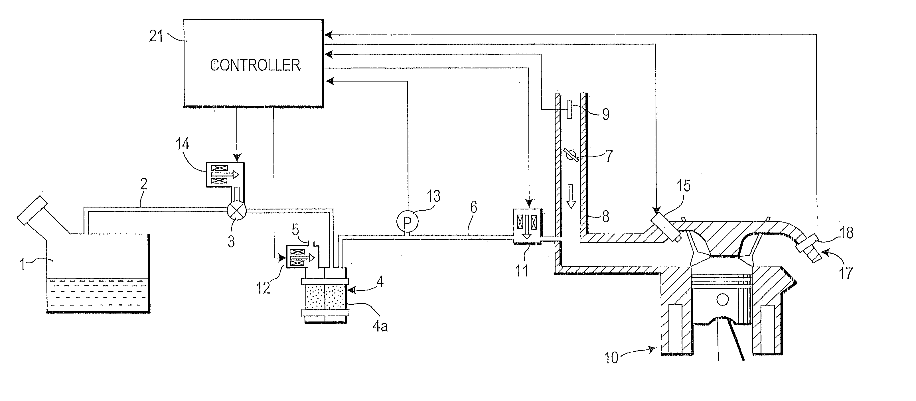
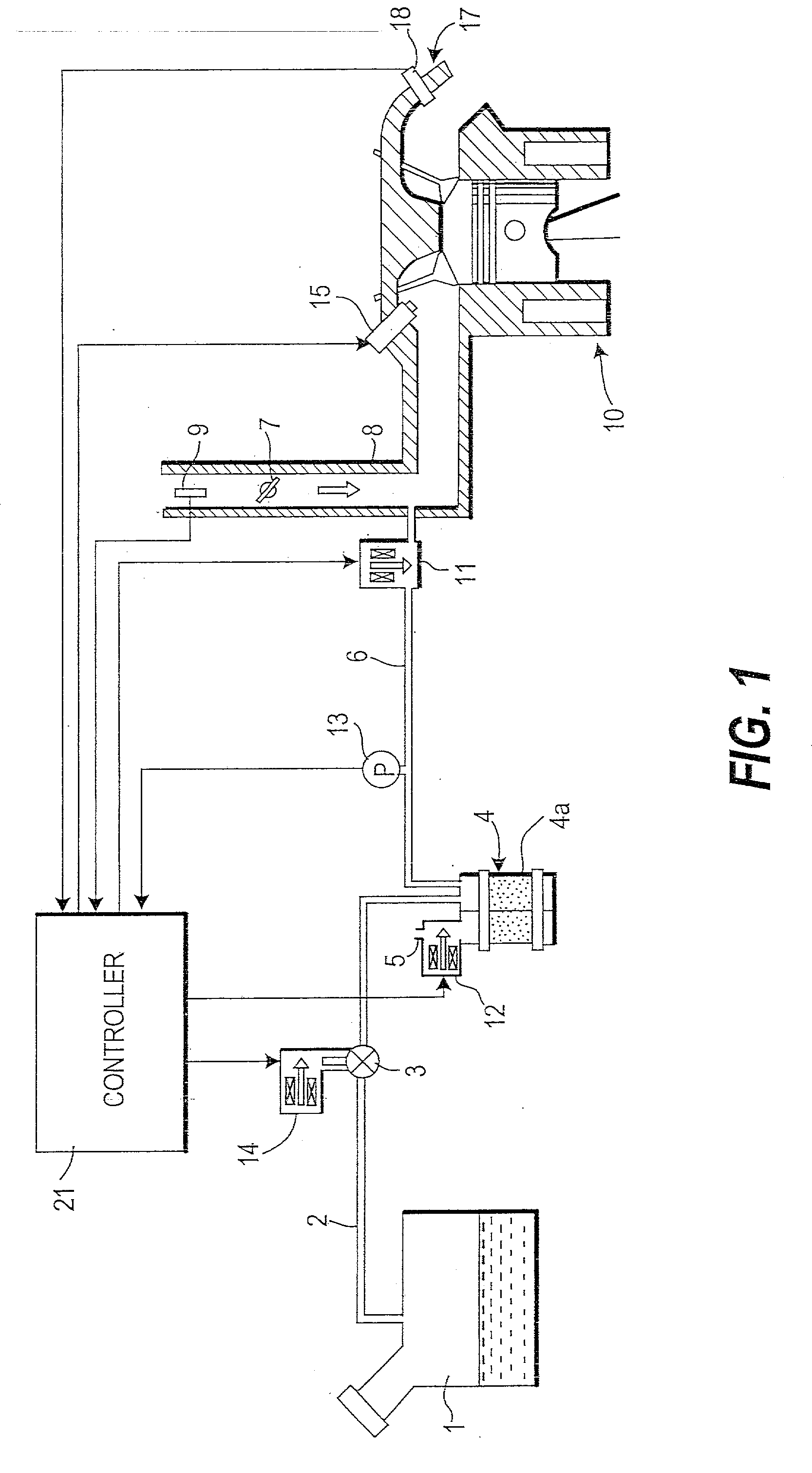
[0025] Referring to FIG. 1 of the drawings, a fuel vapor emission control device of an engine 10, comprises a canister 4, a pipe 2 which connects the canister 4 to a fuel tank 1, and a pipe 6 (purge passage) which connects the canister 4 to an intake passage 8 downstream of a throttle valve 7, and processes fuel vapor generated in the fuel tank 1.

[0026] A vacuum cut valve 3 which opens when the pressure in the fuel tank 1 drops below atmospheric and a bypass valve 14 are provided in parallel in the pipe 2. A purge valve 11 which opens when fuel adsorbed by a fuel adsorbent (activated carbon) 4a in the canister 4 is desorbed, and a pressure sensor 13 which measures the pressure in the pipe 6, are provided in the pipe 6. The canister 4 has an air port 5. The air port 5 is opened and closed by a drain cut valve 12.

[0027] Fuel vapor generated in the fuel tank 1 is led to the canister 4 via the pipe 2, the fuel component alone is adsorbed by the activated carbon 4a in the canister 4, and...


PUM


Abstract

Fuel vapor adsorbed by activated carbon 4a in a canister 4 is introduced to an engine 10 by a manifold vacuum in an intake air passage 8, and burnt. The controller 21 estimates the fuel amount desorbed from the canister 4 during purge, using a canister model (physical model) comprising an equation which computes the adsorption amount and an equation which computes the desorption amount from the adsorption amount and purge rate. An injection pulse width output to injectors 15 is corrected to reduce an air-fuel ratio fluctuation due to the supply of this desorbed fuel to the engine 10.

Description

FIELD OF THE INVENTION[0001] This invention relates to a fuel vapor emission control.BACKGROUND OF THE INVENTION[0002] JP-A-S63-111277 published by the Japanese Patent Office in 1992 discloses a fuel vapor emission control device for an engine. In this fuel vapor emission control device, fuel vapor generated in a fuel tank when the engine has stopped is first adsorbed by activated carbon in a canister, the fuel adsorbed by the activated carbon is desorbed using a manifold vacuum under a predetermined running condition after the engine starts, and the fuel vapor is led into an intake passage downstream of a throttle valve to be burnt.[0003] In the prior art fuel vapor emission control device, the effect on the air-fuel ratio due to the supply of fuel desorbed from the canister to the engine, is treated as a disturbance of the air-fuel ratio, and this disturbance is absorbed by air-fuel ratio feedback control using an oxygen sensor. In other words, if the air-fuel ratio of the engine ...

Claims


Application Information

Patent Timeline
IPC IPC(8): F02D41/00F02D41/40F02M25/08
CPCF02D41/0032F02D41/0042F02D41/0045F02D41/40F02D2041/1433F02M25/08Y02T10/44Y02T10/40
Inventor HAYASHI, TAKANETSUYUKI, TAKESHIKAKIZAKI, SHIGEAKIKOBAYASHI, MASATO
Owner NISSAN MOTOR CO LTD
Why Eureka
Try Eureka