
Process and configuration for providing external upflow/internal downflow in a continuous digester

Inactive Publication Date: 2002-09-19
GLENS FALLS GROUP
View PDF61 Cites 10 Cited by
  • Summary
  • Abstract
  • Description
  • Claims
  • Application Information

AI Technical Summary

Benefits of technology

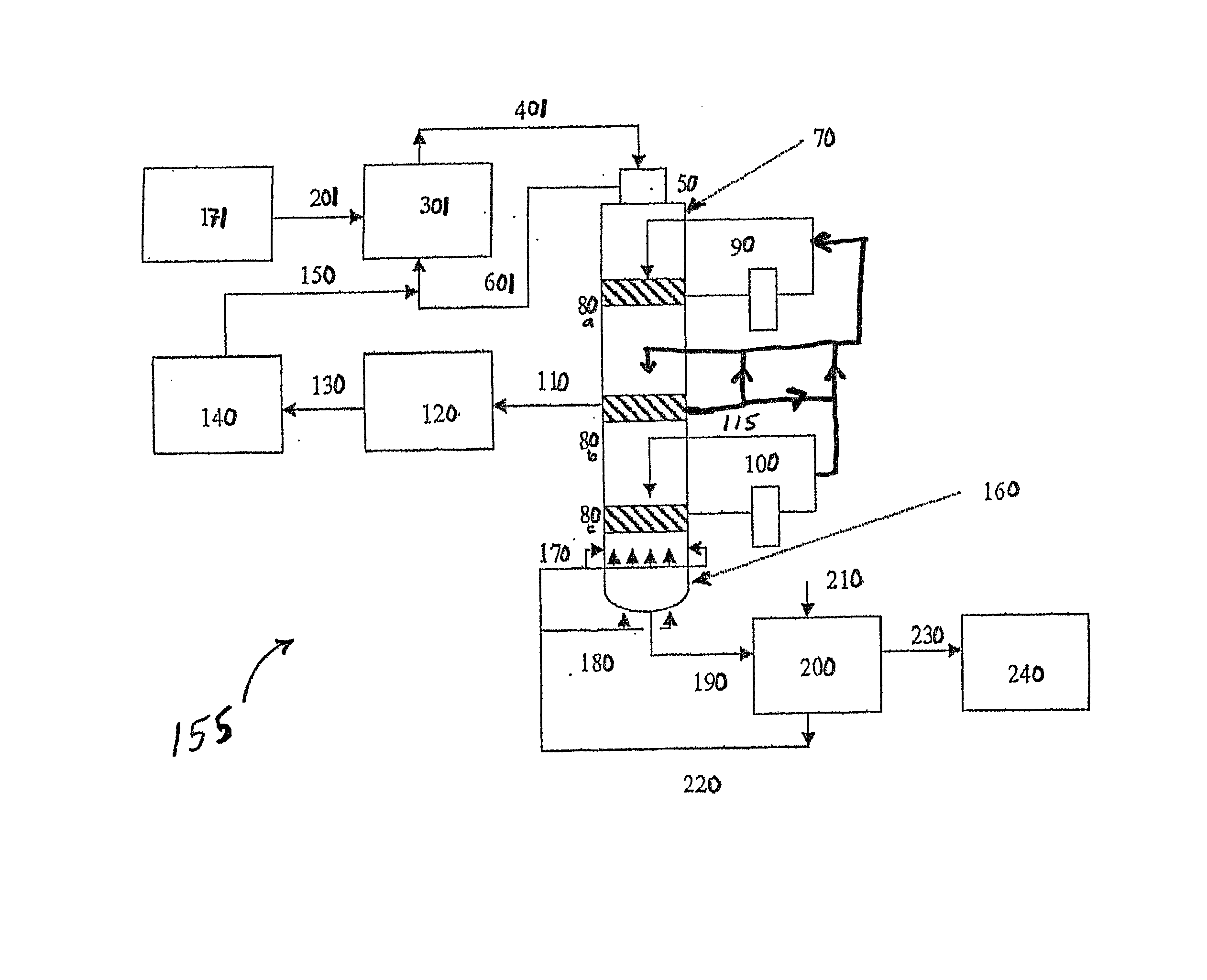
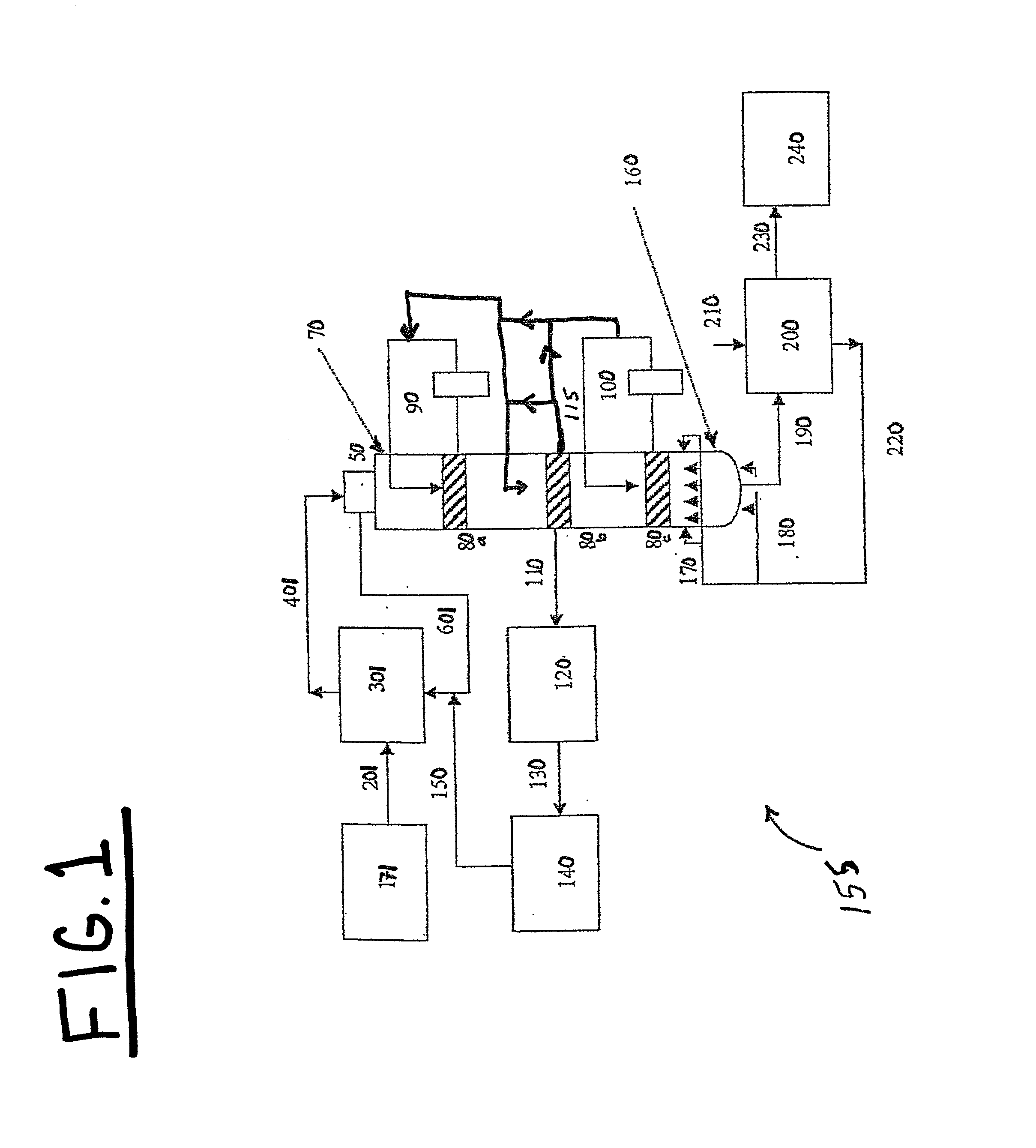
[0014] The present invention relates to continuous digester configurations and processes designed to optimize heat recovery, optimize washing efficiency, optimize operations stability, and obtain the benefits of modified cooking in a continuous digester.

Problems solved by technology

In practice, the "cold blow" digesters were limited in the amount of hot liquor that could be extracted from the screens.
These screens were also prone to plugging.
As a result, the discharge temperature could not be effectively controlled (i.e., lowered).
This can be attributed to numerous factors, perhaps the most important being that there were insufficient economic incentives to mitigate potential risks and development costs.
Nonetheless, the continuous cooking systems of the era did not have reliable, sufficiently high wash zone upflows.
Limitations on the amount of stable upflow that could be obtained make the use of counter-flowing systems for the purposes of cooking unattractive.
In general, the relative amount of upflow is limited by (a) excessive column compaction at the extraction screens, (b) unstable column dynamics in the blow dilution zone, and (c) excessive drag forces in the counter-current zone.
In the final analysis, for digesters built in the 1960's and 1970's, the relative amounts of upflow and extraction flow were severely limited by their inherent design and this led to practical operating constraints.
These problems were made even worse by increased production rates (and thus increased loading rates), and many commercial systems were (and still are) operated at much higher rates than their original design.

Method used


Image

  • Process and configuration for providing external upflow/internal downflow in a continuous digester
  • Process and configuration for providing external upflow/internal downflow in a continuous digester
  • Process and configuration for providing external upflow/internal downflow in a continuous digester

Examples


examples

[0083] The following examples and experimental results are included to provide those of ordinary skill in the art with a complete disclosure and description of particular manners in which the present invention can be practiced and evaluated, and are intended to be purely exemplary of the invention and are not intended to limit the scope of what the inventors regard as their invention. Efforts have been made to ensure accuracy with respect to numbers (e.g., amounts, temperature, etc.); however, some errors and deviations may have occurred. Unless indicated otherwise, temperature is in .degree. C. or is at ambient temperature, and pressure is at or near atmospheric.

[0084] An extended digester trial was performed, wherein the digester process configuration was changed from upflow to downflow modified cooking. The primary objective of the trial was to quantify the effect of downflow cooking on overall mill operations and then use this information to perform a cost-benefit-risk analysis ...


PUM

PropertyMeasurementUnit
Specific volumeaaaaaaaaaa
Fractionaaaaaaaaaa
Fractionaaaaaaaaaa

Abstract

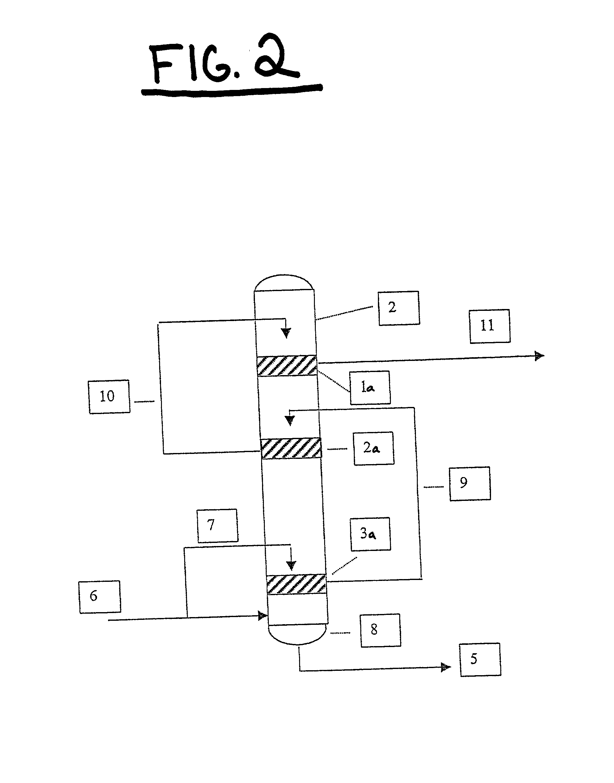
A continuous digester configuration and process for continuously cooking and digesting cellulosic material and producing cellulosic pulp is disclosed. The digester configuration comprises a plurality of jump-stage recirculations located along the length of a continuous digester vessel, wherein each of the jump-stage recirculations moves extracted liquor from one elevation of the digester vessel and re-introduces the liquor at a higher elevation in the vessel to maintain an internal liquor downflow substantially throughout the entire digester vessel. The process for continuously cooking and digesting cellulosic material comprises maintaining an internal concurrent liquor downflow substantially throughout the continuous digester vessel, wherein the internal liquor downflow does not exceed 400 gallons per ton of b.d. wood feed.

Description

CROSS-REFERENCE TO RELATED APPLICATION[0001] This application claims priority to and the benefit of U.S. patent application Ser. No. 60 / 240,659, filed Oct. 16, 2000, which is hereby incorporated by reference in its entirety.FIELD OF THE INVENTION[0002] This invention relates generally to continuous digesters that digest cellulosic fibrous material and produce cellulosic pulp. More particularly, this invention relates to an improved digester configuration and process for use in and with a continuous digester. The configuration and process of this invention produce a heretofore-unseen internal con-current flow or downflow in the digester vessel.BACKGROUND OF THE INVENTION[0003] Continuous digesters for production of pulp were developed in the 1940's and commercialized in the 1950's. Original continuous digester designs were completely con-current (downflow of chips, chip-bound-liquor, and liquor). Digesters sold in the 1950's were described as "cold blow" digesters in that they had a ...

Claims


Application Information

Patent Timeline
IPC IPC(8): D21C7/14
CPCD21C7/14
Inventor MARCOCCIA, BRUNO S.PROUGH, JAMES ROBERTTORREGROSSA, LOUIS O.
Owner GLENS FALLS GROUP
Learn More