Drive wheel for track apparatus

a technology for driving wheels and track equipment, which is applied in the direction of hoisting equipment, vehicle maintenance, vehicle cleaning, etc., can solve the problems of affecting the operation of the drive wheel, the lugs of the track are substantially unsupported, and the vehicles entering the field become buried in mud, so as to facilitate the manufacture of the drive wheel, the effect of reducing or substantially eliminating the harmful torsional forces

Inactive Publication Date: 2002-09-19
ATI TECH INC
View PDF8 Cites 21 Cited by
  • Summary
  • Abstract
  • Description
  • Claims
  • Application Information

AI Technical Summary

Benefits of technology

[0011] Another object of this invention is to provide a track apparatus drive wheel which does not damage the flexible track during extended use.
[0012] Another object of this invention is to provide a track apparatus drive wheel which minimizes shearing forces on the lugs of flexible tracks used on such track apparatus.
[0013] Still another object of this invention is to provide a track apparatus drive wheel which minimizes or eliminates the torsional forces referred to above.
[0014] Yet another object of this invention is to provide a track apparatus drive wheel which effectively drives the flexible belt in difficult work conditions.
[0015] Another object of this invention to provide a track apparatus drive wheel which is simple and inexpensive to manufacture.

Problems solved by technology

As a result, the tires of such vehicles tend to compact the soil in the fields or other ground surfaces.
Compacted soil discourages growth of crops planted in the fields which need loose soil to flourish, and ground surface compaction is often undesirable for other reasons as well.
In addition, since fields and other work sites are often wet due to rain or watering, vehicles which enter the fields become bogged down in the mud due to the fact that there is such a small tire area in contact with the ground.
In such prior apparatus, the terminal surfaces of the track lugs do not engage the drive wheel; in other words, the track lugs are substantially unsupported.
All of the driving force is imparted on the track lugs by the drive projections of the drive wheel, and this shear force, imparted as it is on substantially unsupported track lugs, tends to cause cracking and premature wear of the track lugs.
However, when there is a tendency toward track misalignment, the side structure of the drive wheel engages the lateral surfaces of the track lugs, and imposes torsional and further shearing forces on such track lugs.
These torsional and shearing forces exacerbate the resulting cracking and premature wear of the track lugs.

Method used


Image

  • Drive wheel for track apparatus
  • Drive wheel for track apparatus
  • Drive wheel for track apparatus

Examples


Embodiment Construction

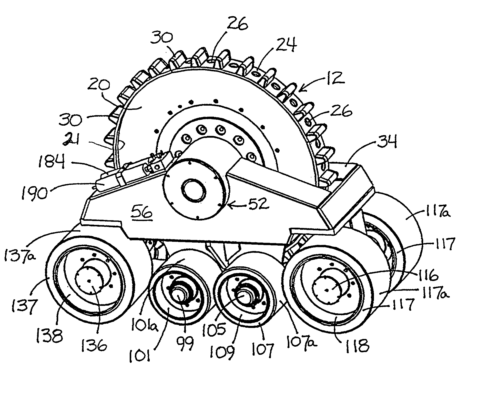
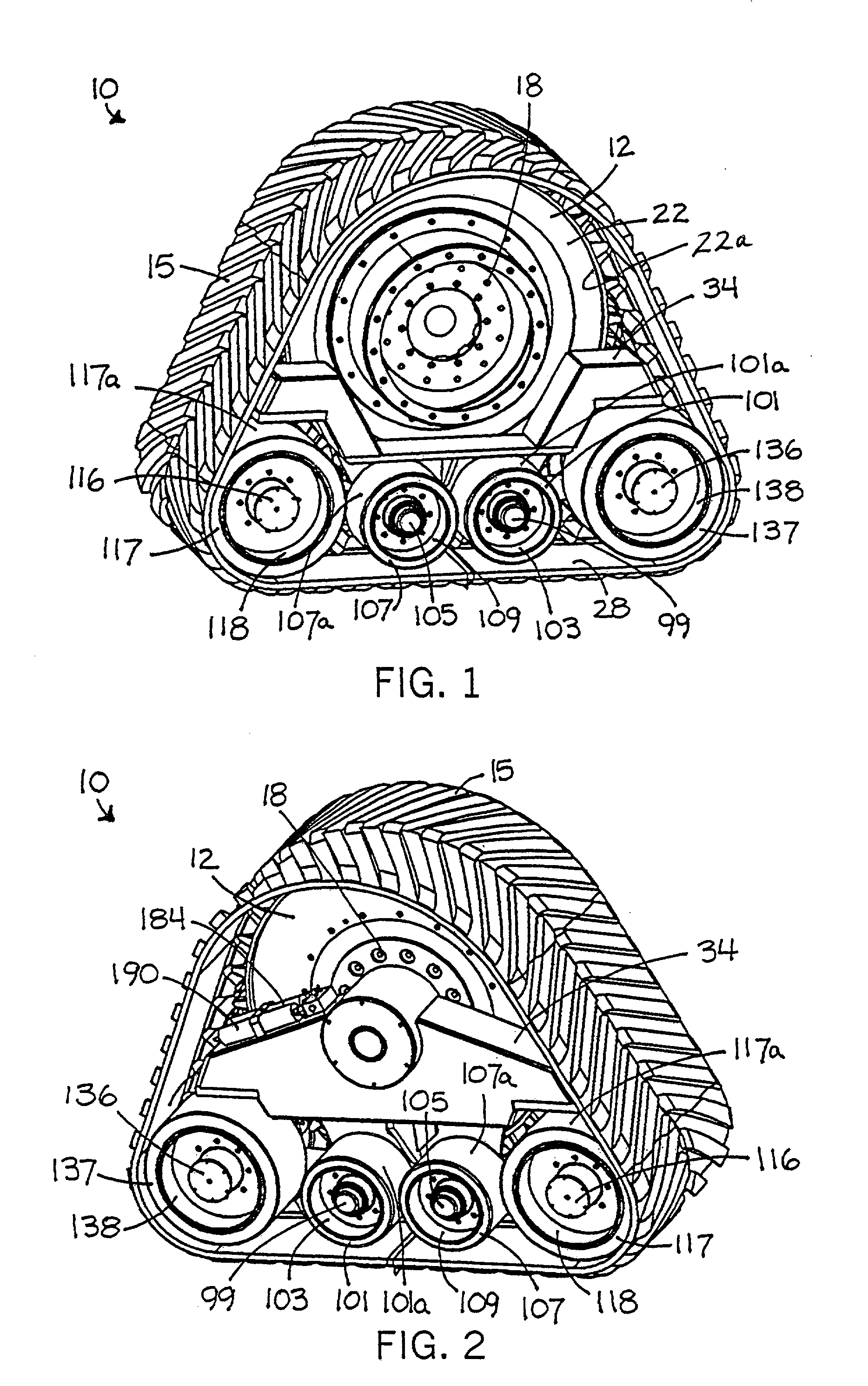
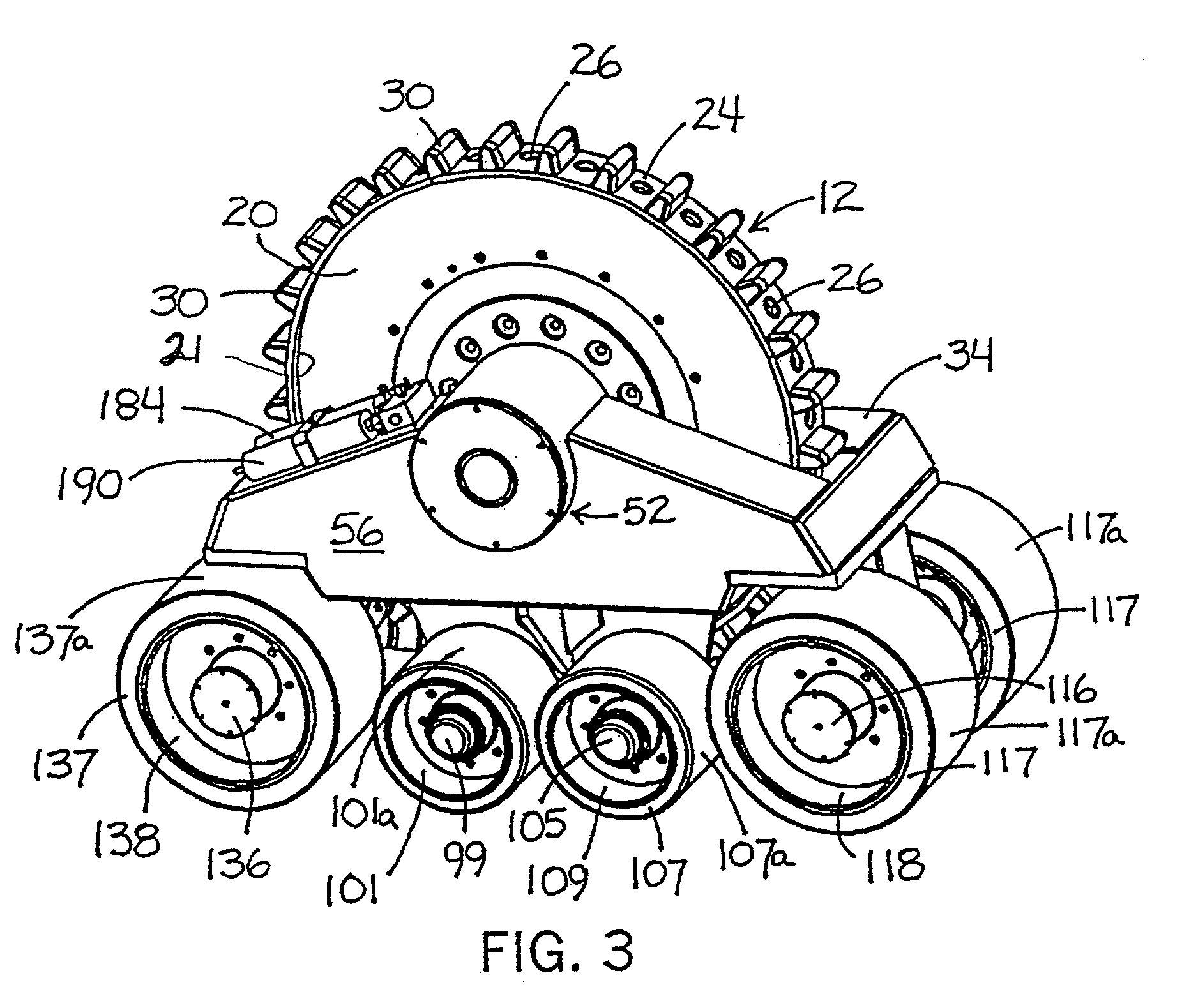
[0035] Referring to FIG. 1-2, a track apparatus in accordance with this invention is generally designated by the reference numeral 10. In a preferred embodiment, track apparatus 10 is mounted on an axle (not shown) of an agricultural vehicle (e.g., a tractor or a combine), a construction vehicle or other work vehicle. It is within the scope of the present invention for track apparatus 10 to be mounted on a wide variety of vehicles.

[0036] Track apparatus 10 includes a drive wheel 12 which is mountable to the axle of a vehicle for rotational movement therewith in order to drive a flexible track 15. As best seen in FIG. 1, in a preferred embodiment it is intended to mount track apparatus 10 to a vehicle having a planetary axle. However, it is contemplated to mount track apparatus 10 to a bar axle or other type of axle without deviating from the scope of the present invention.

[0037] Referring to FIG. 2, drive wheel 12 includes a first set of circumferentially spaced attachment openings ...


PUM


Abstract

A drive wheel engaged with flexible track of track apparatus mountable on a vehicle axle, the drive wheel including a peripheral portion which, between radially-extending drive members, has outwardly-facing lug-engagement surfaces in position for engagement with the distal surfaces of the track lugs, to extend the useful life of flexible track. Preferred embodiments have spaces facilitating removal of debris. Certain preferred lug-engaging surfaces are provided by peripherally-spaced cross-members. The drive wheel is preferably free of side structure, allowing track lugs to adjust precise positions of engagement with lug-engagement surfaces.

Description

RELATED APPLICATION[0001] This is a continuation-in-part of U.S. Ser. No. 09 / 627,862, filed Jul. 28, 2000, now U.S. Pat. No. ______.FIELD OF THE INVENTION[0002] This invention relates generally to track apparatus for vehicles. In particular, this invention relates to track apparatus of the type for use in place of a vehicle wheel and, more particularly, to apparatus for driving the flexible tracks of such apparatus during vehicle operation.BACKGROUND OF THE INVENTION[0003] Agricultural vehicles such as tractors, combines and the like are commonly used in agricultural fields for a variety of jobs, and construction vehicles and other large work vehicles are used for many different jobs on a variety of ground surfaces. Typically, these vehicles have tires on which the vehicles are supported on the ground. These kinds of large vehicles are quite heavy, their weight of is distributed to a relatively small area by the vehicle the tires. As a result, the tires of such vehicles tend to comp...

Claims


Application Information

Patent Timeline
Patent Type & Authority Applications(United States)
IPC IPC(8): B62D55/04B62D55/104B62D55/12B62D55/125B62D55/30
CPCB62D55/04B62D55/104B62D55/12B62D55/125B62D55/305
Inventor JUNCKER, DAVID L.KAHLE, GLENN W.RESHAD, JAMSHEED
Owner ATI TECH INC
Why Eureka
Try Eureka