Computer system

Active Publication Date: 2002-09-26
ORACLE INT CORP
View PDF29 Cites 48 Cited by
  • Summary
  • Abstract
  • Description
  • Claims
  • Application Information

AI Technical Summary

Benefits of technology

0095] In order to increase the likelihood of correctly identifying the faulty group of devices, in some embodiments, the fault response processor may be operable to identify from a time of arrival of the fault reports from the device drivers an analysis interval, and to estimate the location of the faulty device from the fault reports which were generated within the analysis interval.
0096] When a fault occurs within a device, causing a change in the operational status within that device, the fault reports generated by device drivers embodying the present invention can tend to generate fault reports at a rate which can be loosely

Problems solved by technology

If a computer system goes down, the inconvenience and loss of revenue and indeed life endangering effects can be substantial.
Although redundant processing sets within a computer system provide a facility for detecting, diagnosing and recovering from errors in the processing sets, the utility devices within the computer system, including the connecting buses and peripheral buses, may fail from time to time.
A device failure can cause disruption in the operation of the computer system, and may even cause the computer system to go down.
When there

Method used


Image

  • Computer system
  • Computer system
  • Computer system

Examples


example

[0063] FIG. 8 shows that the drivers for both devices A and C have positively identified their device as having a fault, FR.1, FR.2. In this case the evidence from the driver for device C, FR.2 is discounted, because the fault report was likely to have been triggered as a result of reading bad data through A, although this could not be determined at the time the fault was reported.

[0064] Phase II

[0065] In the second phase of the operation the device tree is analysed by the AFR to identify a set of faulty FRUs with a non-zero probability of having a fault. For example, if a device node is down and indicating that it is the location of the fault then there is a 100% probability that the FRU containing that device has a fault. If a device node is down and is indicating a fault in its data path and an ancestor is indicating an external fault then the fault is deemed to lie in a FRU containing either of the two devices or a FRU in between (if there is one). Hence a 100% probability is as...

example a

[0069] Consider the AFR constructed device tree in FIG. 9. The driver for device A has reported an external fault FR.3 and the driver for device C has positively identified an internal fault FR.4. The device C is unambiguously identified as being in error (P=100%). The FRU containing this device is therefore considered to be faulty.

example b

[0070] FIG. 10 shows that the driver for device A has reported an external fault FR.5 and the driver for device C have reported a data path fault FR.6. The analysis modules form a probability metric that one of the FRUs contains a faulty device, or that the fault lies somewhere between devices A and C (possibly including the devices themselves). In this case the fault probability that a FRU contains a faulty device is weighted between the number of devices on the FRU. For the present example, if the devices A, C are embodied on the same FRU, then this FRU is assigned a 100% fault probability. If however the two devices are embodied on different FRUs then each FRU is assigned a fault probability of 50%. However, if the fault probability metric generated does not exceed the predetermined probability threshold then no conclusion may be drawn as to the faulty FRU. An improved estimate of the identity of the faulty FRU can be made from analysis performed in accordance with phase III.

[007...


PUM


Abstract

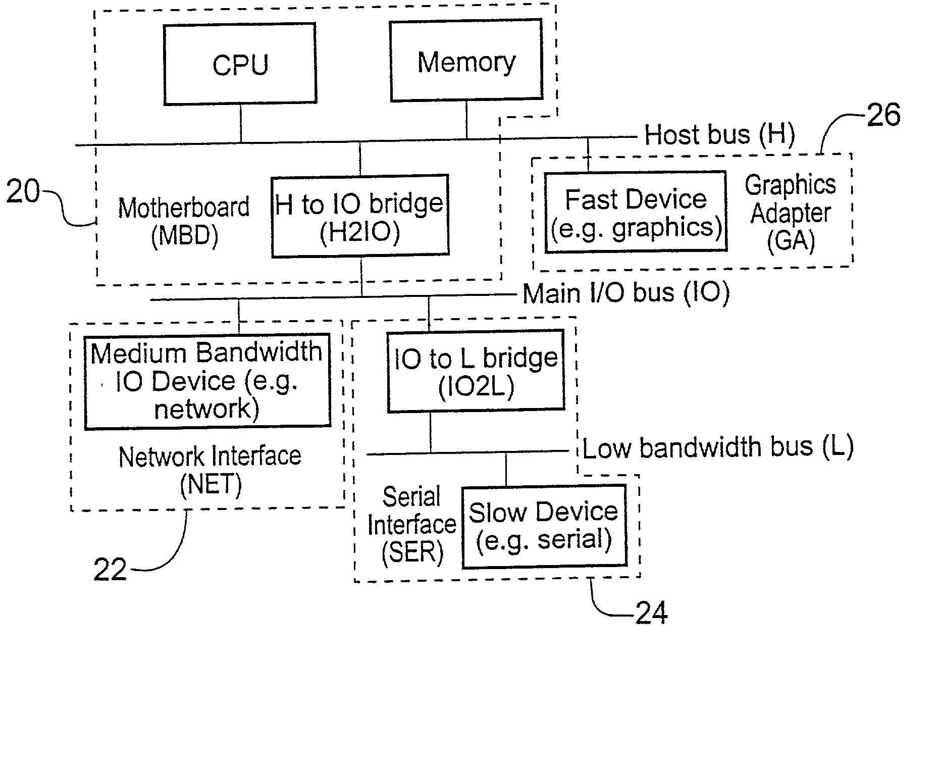
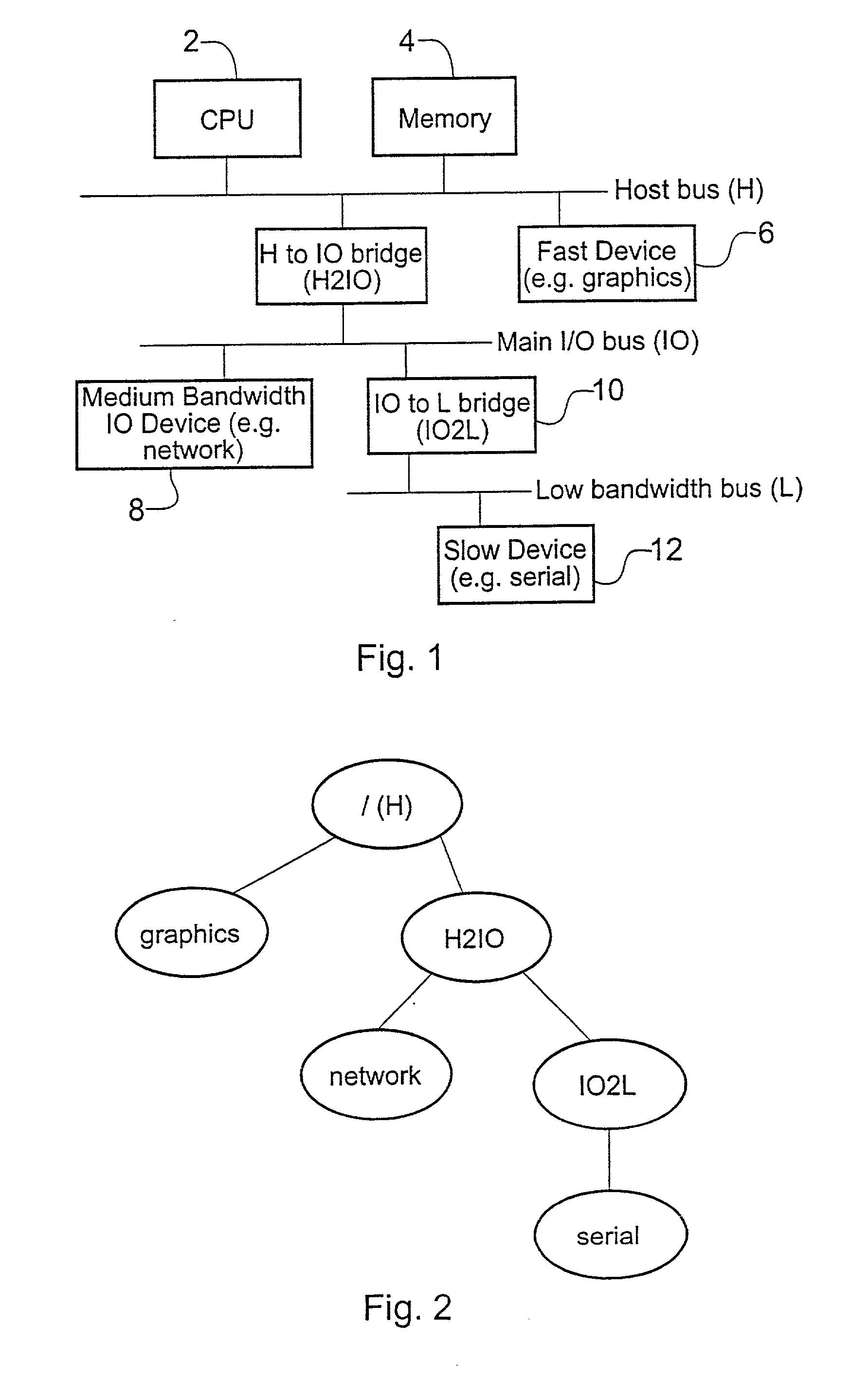
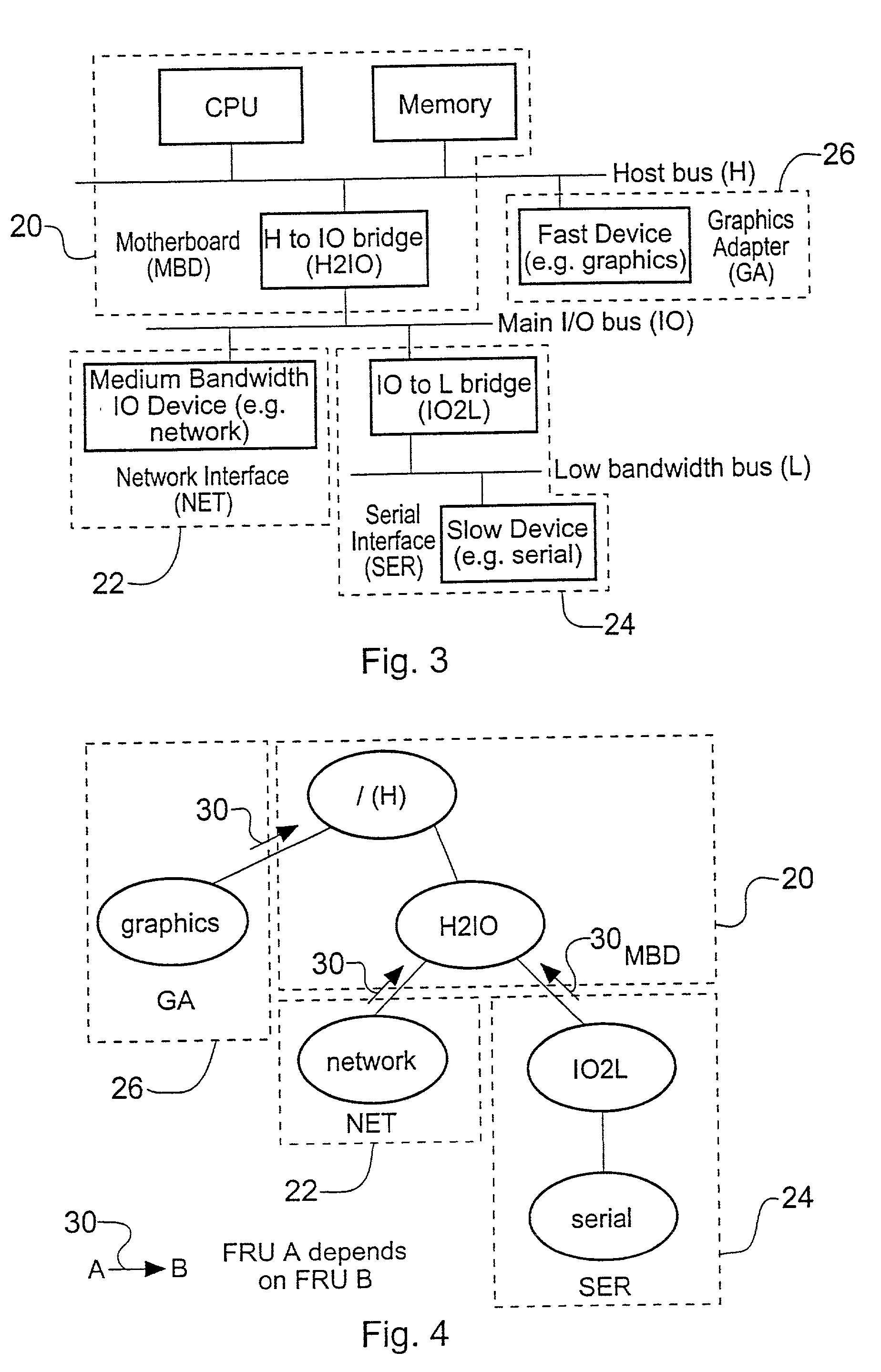
A computer system comprises a processor (2), memory (4) and a plurality of devices (6, 8, 10, 12), the processor (2) and the memory (4) being operable to effect the operation of a fault response processor (AFR), and a device driver (GRAPHICS, NETWORK, H2IO, IO2L, SERIAL) for each of the devices. The fault response processor (AFR) is operable to generate a model (81) which represents the processor (2), the memory (4) and the devices (6, 8, 10, 12) of the computer system and the inter-connection of the processor (2), memory (4) and the devices (GRAPHICS, NETWORK, H2IO, IO2L, SERIAL). The device driver (GRAPHICS, NETWORK, H2IO, IO2L, SERIAL) for each of the devices (6, 8, 10, 12) is arranged, consequent upon a change of operational status of the device, to generate fault report data indicating whether the change of status was caused internally within the device or externally by another connected device. The devices of the computer system may be formed as a plurality of Field Replaceable Units (FRU). The fault response processor (AFR) is operable, consequent upon receipt of the fault reports from the device drivers (GRAPHICS, NETWORK, H2IO, IO2L, SERIAL) to estimate the location of a FRU containing a faulty device by applying the fault indication to the model (81). In other embodiments the fault report data includes direction information indicating a connection between the device and the other connected device which caused the external fault. Having identified the faulty device the FRU may be replaced, thereby minimizing down time of the computer system.

Description

[0001] The present invention relates to computer systems.[0002] There are many fields in which mankind has become reliant on computers to perform valuable and sometimes essential functions. The reliance on computer systems demands that the down time of computer systems is as small as possible. The down time of a computer system is a period during which a computer system is inoperable as a result of a fault in the system. If a computer system goes down, the inconvenience and loss of revenue and indeed life endangering effects can be substantial. As result, the reliability of computer systems is arranged to be as high as possible.[0003] In a co-pending U.S. patent application, Ser. No. 09 / 097,485, a fault tolerant computer system is disclosed in which multiple processing sets operate to execute substantially the same software, thereby providing a amount of redundant processing. The redundancy provides a facility for detecting faults in the processing sets and for diagnosis and automat...

Claims


Application Information

Patent Timeline
IPC IPC(8): G06F11/07
CPCG06F11/0727G06F11/079
Inventor DURRANT, PAULHANSON, STEPHEN R.GORDON, DAVID S.MOIIN, HOSSEIN
Owner ORACLE INT CORP
Why Eureka
Try Eureka