

Multi pre-focused annular array for high resolution ultrasound imaging
- Summary
- Abstract
- Description
- Claims
- Application Information
AI Technical Summary
Problems solved by technology
Method used
Image

Examples
Embodiment Construction
[0025] A particular embodiment of the invention will be explained with reference to the Figures.
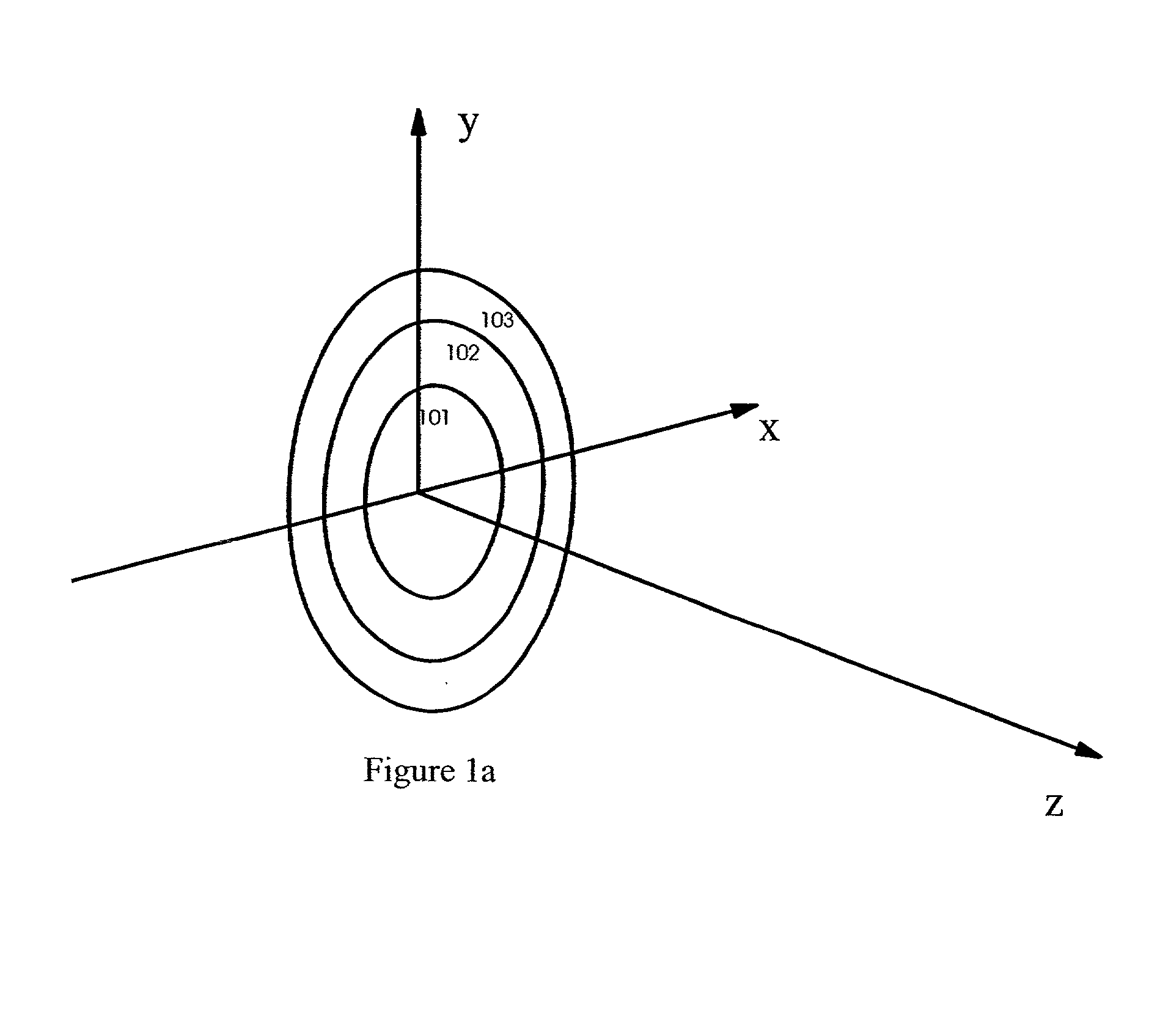
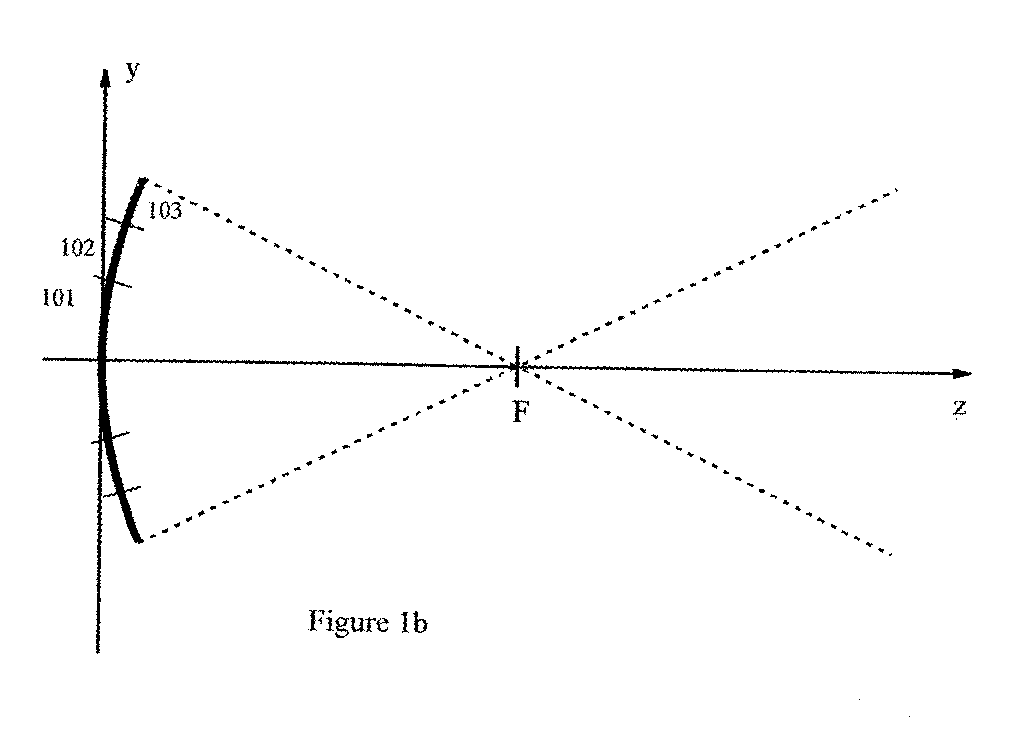
[0026] FIG. 1a shows a schematic front view of an example of a typical prior art annular array, where the coordinate x denotes the azimuth direction which is the 2D scan plane direction, the coordinate y denotes the elevation direction, and the coordinate z denotes the depth. In this example, the elements are composed of a center disc 101 with two concentric annuli 102 and 103. By shaping the array as a spherical shell with center at a depth F, the array is pre-focused to this depth, as illustrated in FIG. 1b. A lens of a material with acoustic velocity different from that of the load material, can also be used for the pre-focusing.
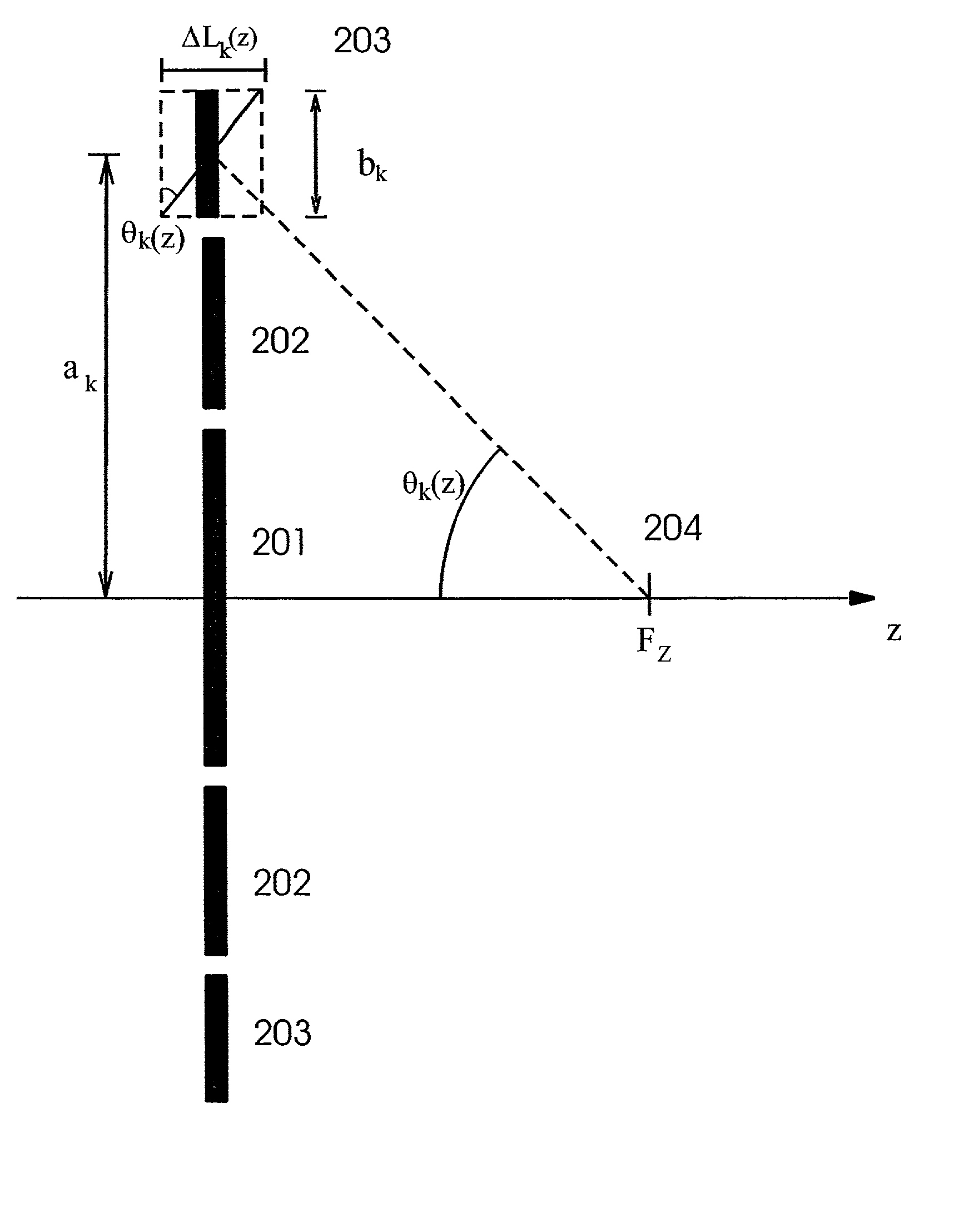
[0027] FIG. 2a shows a a cross section in the elevation direction of plane annular array, depicting the cross section of a set of elements 201, 202, and 203. A requirement for adequate participation of an element in the formation of a focused aperture, is that ...
PUM
 Abstract
Description
Claims
Application Information