Ultrasound Machine Providing Composite Image Data

a composite image and ultrasonic technology, applied in the field of ultrasonic imaging equipment, can solve problems such as lack of well-defined image corners, and achieve the effect of improving image quality and improving image quality

Active Publication Date: 2014-12-18
WISCONSIN ALUMNI RES FOUND
View PDF6 Cites 6 Cited by
  • Summary
  • Abstract
  • Description
  • Claims
  • Application Information

AI Technical Summary

Benefits of technology

[0006]The problem of intra-image motion is addressed by subdividing each of the images into portions that are then separately registered. In this way the assumption of affine transformations can be piecewise correct. Independent registration of these portions is accommodated by an interpolation process when the portions are combined.
[0031]The weighting of the images in combining images obtained at different ultrasound frequencies may provide a weighting dependent on a cumulative value of attenuating tissue traversed by the ultrasound beam in passing from the ultrasonic transducer to material located at a point of the given data.

Problems solved by technology

These obstacles include: (1) motion among structures in the material being imaged, this intra-image motion undercutting the assumption that the images are related in a single affine mapping (that is, are related to each other by simple rotation, translation or scale changes) and (2) the lack of well-defined image corners or other consistent registration features allowing the images to be properly aligned before combination.

Method used


Image

  • Ultrasound Machine Providing Composite Image Data
  • Ultrasound Machine Providing Composite Image Data
  • Ultrasound Machine Providing Composite Image Data

Examples


example i

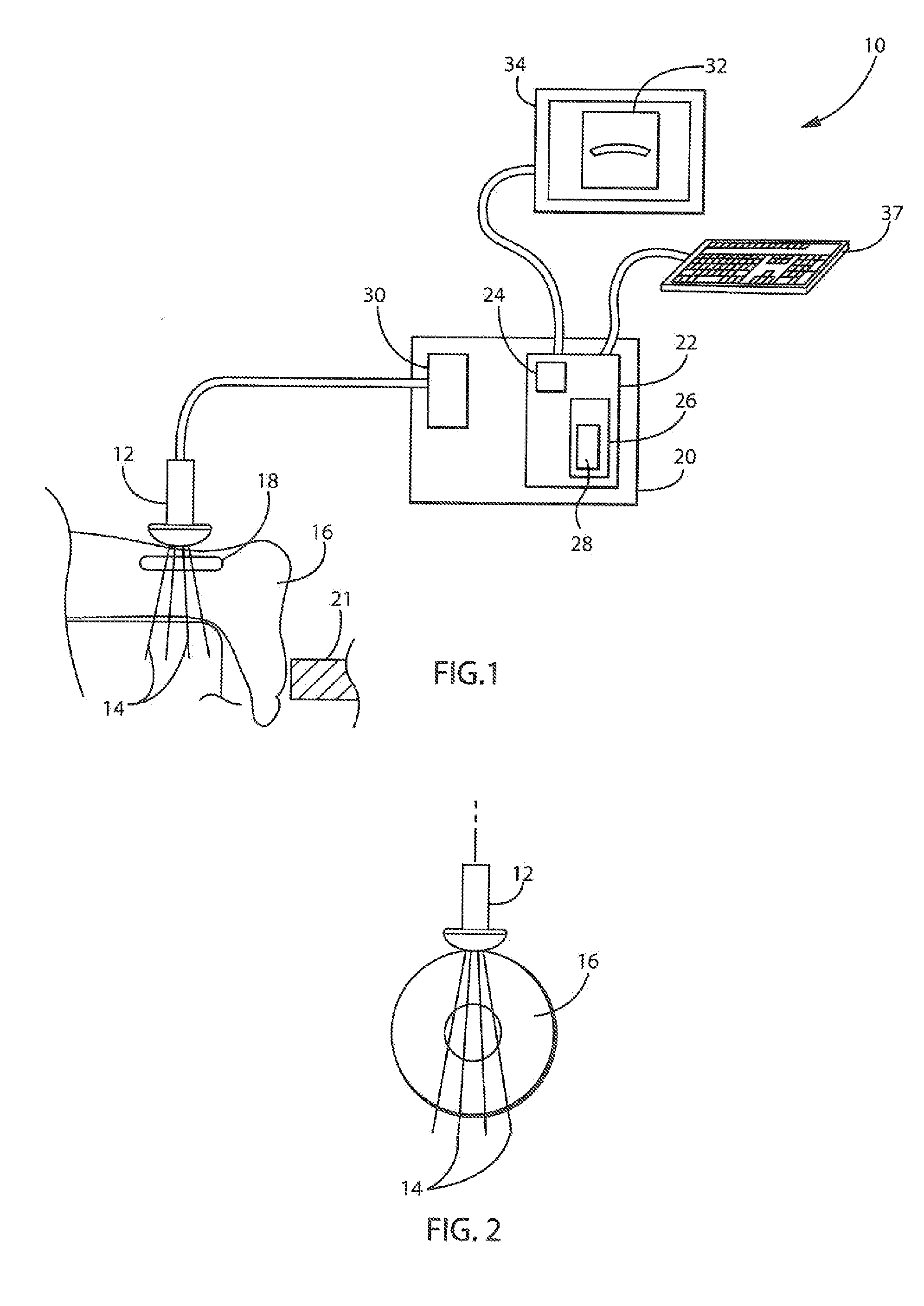
[0078]Three porcine digital flexor tendons, completely excised from surrounding tissue but with an intact bone-tendon insertion site, were mechanically tested in a servohydraulic test system (MTS 858, Minneapolis, USA). Original tendon length was recorded for strain calculations. A bead of graphite-impregnated silicone gel was placed on the surface of the tendons to provide a non-deforming image segment.

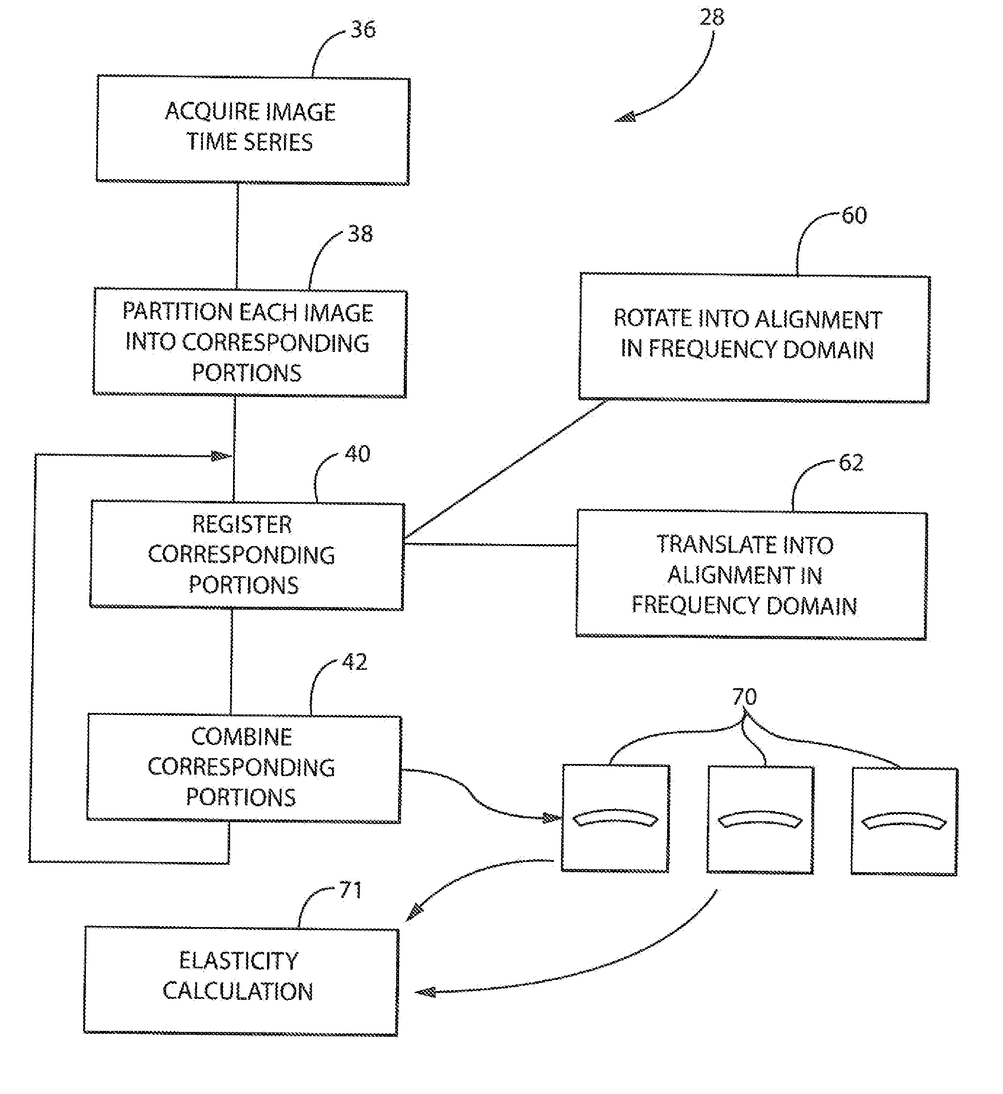
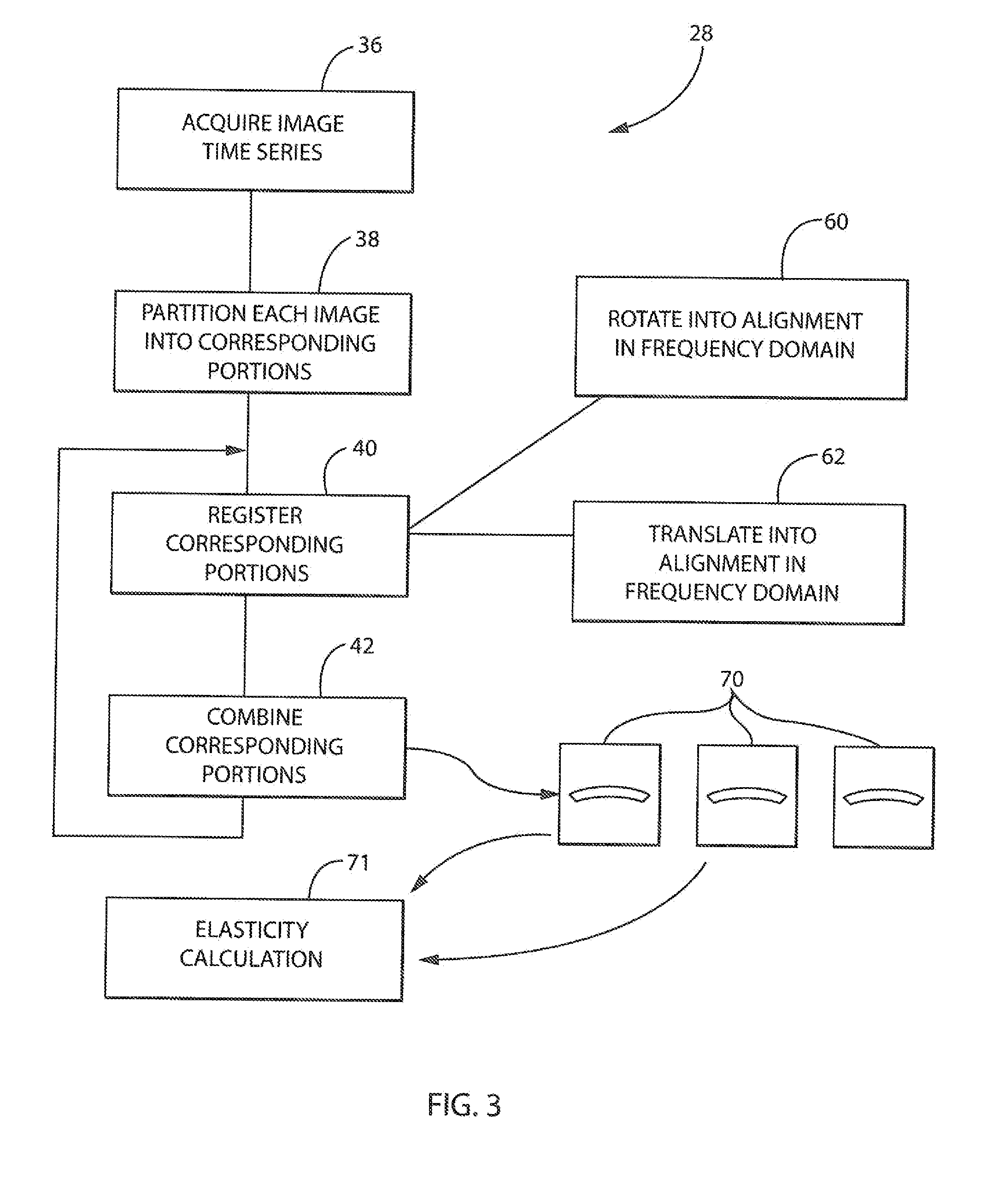
[0079]Tendons were incrementally stretched, 0.1 mm at a time, inside a saline-filled bath (which facilitated transmission of ultrasound waves), to a non-damaging physiological strain (<6.5% strain). Four ultrasound images, one each at 8, 10, 12, and 13 MHz, were captured at each stretch increment (GE Logiqe, Fairfield, USA). Unprocessed images were combined into four videos (one at each frequency) to produce “raw video.” Images were subjected to processing to produce a high-resolution image followed by a combination of high-resolution images into high-definition images as discussed a...

example ii

[0082]A silicone breast tumor phantom (provided by SuperSonic Imagine, Aix-en-Provence, France) was mechanically compressed in a servohydraulic test system (MTS 858, Minneapolis, Minn., USA). The “breast” was incrementally compressed, 0.1 mm at a time, with the ultrasound transducer positioned immediately over the “tumor.” Four ultrasound images, one each at 8, 10, 12, and 13 MHz, were captured at each compression increment. Unprocessed images were combined into four videos (one at each frequency); this is the “raw video.” Raw video images were subjected to processing to produce a high-resolution image followed by a combination of high-resolution images into high-definition, high-resolution images as discussed above to produce “processed video 1”. The raw video was then combined in the alternative order to first reduce high-definition video and then combine the high-definition video into high-definition, high-resolution video to produce “processed video 2”.

[0083]Each of the videos (...


PUM


Abstract

An ultrasound imaging system combines successive images of a time series to produce high-resolution ultrasound. A piecewise registration process and deemphasizing of high-frequency spatial components may be used to aid in the combination process. A high-definition image may be obtained with or separately from this process by combining different images obtained with different ultrasound frequencies. The images are weighted to accentuate the contribution of high-frequency ultrasound data at the leading edge of imaged structure.

Description

STATEMENT REGARDING FEDERALLY SPONSORED RESEARCH OR DEVELOPMENTCROSS REFERENCE TO RELATED APPLICATIONBACKGROUND OF THE INVENTION[0001]The present invention relates to ultrasonic imaging equipment and, in particular, to a method and apparatus providing higher quality ultrasound images by combining data from several time displaced and / or several frequency displaced images.[0002]Ultrasonic imaging provides a mapping of ultrasonic echo signals to an image plane where the magnitude of the reflected ultrasound wave (“echo”) is mapped to brightness of pixels in the image. Such images may reveal structures within the body as delineated by the increased reflection that occurs at the interface between materials of dissimilar acoustic properties, for example, different tissue types.[0003]Greater insight into the physical properties of the material being imaged may be obtained by using the ultrasound images for elasticity measurements. In one type of elasticity measurement termed “quasi-static ...

Claims


Application Information

Patent Timeline
Patent Type & Authority Applications(United States)
IPC IPC(8): A61B8/08A61B8/14A61B8/00
CPCA61B8/5253A61B8/14A61B8/463A61B8/0891A61B8/485A61B8/5246G06T2207/10016G06T2207/10132G06T2207/20021G06T2207/30004G06T7/37
Inventor VANDERBY, RAYWU, MON-JUKARLS, JOSEPHKUEHL, SARAHSETHARES, WILLIAM A.
Owner WISCONSIN ALUMNI RES FOUND
Why Eureka
Try Eureka