Blender cutter

a cutting tool and blade technology, applied in the field of blade cutters, can solve the problems of inconvenient processing of material by cutters, inefficient circulation of material being processed, and inconsistent particle size of processed material

Inactive Publication Date: 2002-10-03
HAMILTON BEACH BRANDS
View PDF0 Cites 63 Cited by
  • Summary
  • Abstract
  • Description
  • Claims
  • Application Information

AI Technical Summary

Benefits of technology

0005] Accordingly it is an object of the present invention to overcome the foregoing drawbacks and provide a cutter

Problems solved by technology

One problem with many blenders is that their cutters process material at the bottom of the blender jar only.
There is inefficient circulation of the material that

Method used


Image

  • Blender cutter
  • Blender cutter
  • Blender cutter

Examples


Embodiment Construction

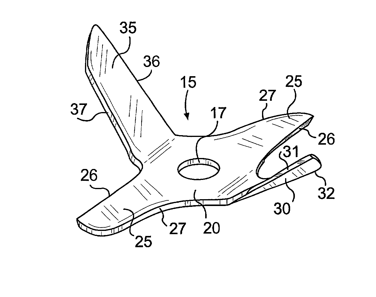
[0015] The present invention includes a cutter having blades that are asymmetrically angled and pitched in order to best circulate the material to be processed in a blender and to evenly process that material.

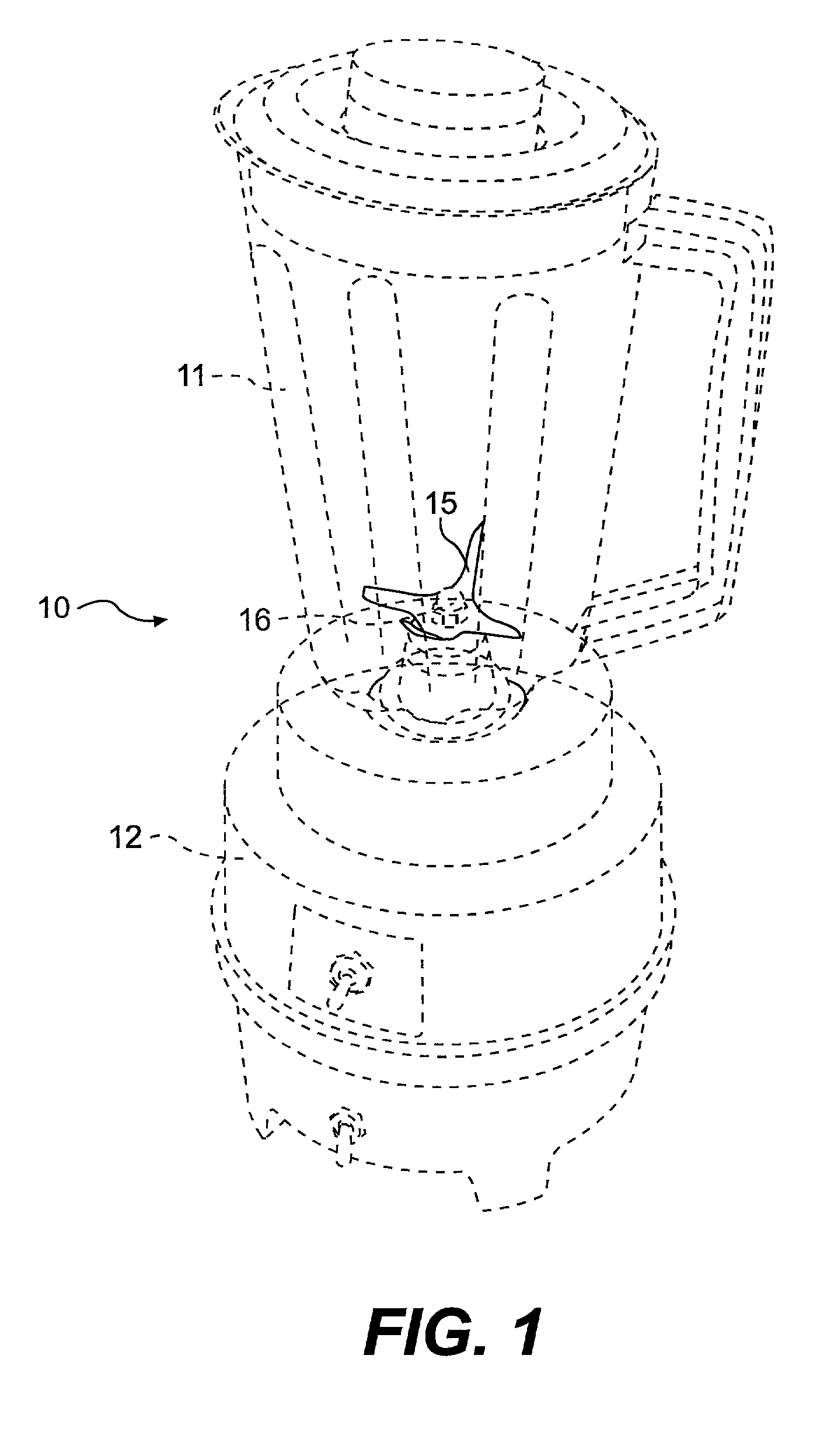
[0016] Turning first to FIG. 1, there is shown a blender 10 made up of a blender jar 11 mounted onto a housing 12 in which is positioned a motor (not shown). The motor turns a drive shaft onto which is connected the cutter 15 by the nut 16. Details with respect to the motor, drive shaft, clutch and bearing assemblies are not shown. They are conventionally assembled in order to drive the cutter 15 in a rotatable fashion to process material that is received in the blender jar 11.

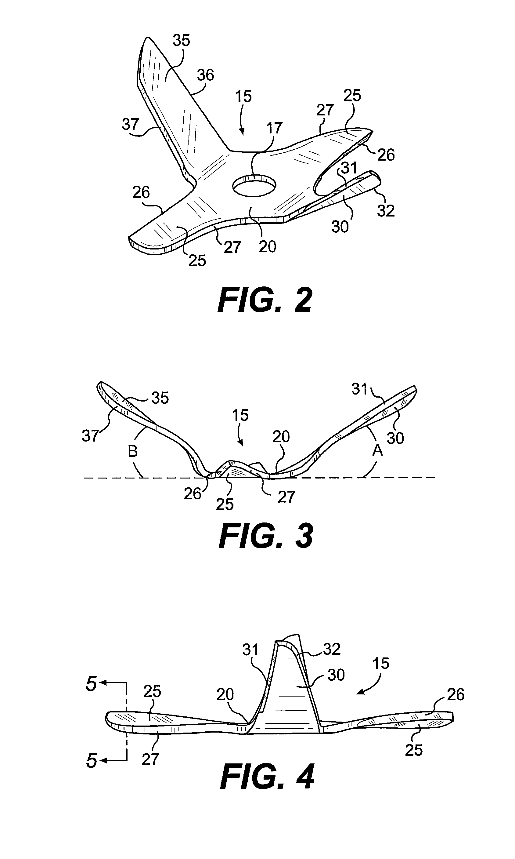
[0017] Turning now to FIG. 2, there is shown the cutter 15 that was also seen in FIG. 1. The cutter 15 has a hub portion 20 which defines a circular aperture 17 which allows the drive shaft (not shown) to be connected to the cutter. The hub portion 20 defines a horizontal plane. Extending outwardly from t...


PUM


Abstract

A cutter for use in a blender includes a central hub portion defining a horizontal plane. First and second pairs of blades extend outwardly from the hub portion. The first pair of blades is oriented on opposite sides of the hub portion and the blades lie in substantially the same horizontal plane as the hub portion. The second pair of blades is oriented on opposite sides of the hub portion and the blades extend upwardly from the horizontal plane of the hub portion, and further wherein the angles of upward extension of each of the second pair of blades is asymmetric. Further, each blade of the first set of blades has a cutting edge and trailing edge, and each blade of the first set of blades is pitched so that there is a downward slope from the cutting edge to the trailing edge.

Description

[0001] This invention relates to a cutter for a blender. Specifically, this invention relates to the angles and pitches of the blades of a cutter.BACKGROUND OF THE INVENTION[0002] There are many different types of blenders that have been available for many years. Each blender is adapted to cut, chop, mix, blend, liquify, etc. Many types of cutters have been used in connection with these blenders to accomplish these food processing purposes.[0003] Known cutters include a wide range of symmetric and asymmetric blade configurations. The blades are angled in some cases. Further, known cutters are often made of multiple separate blade components that are joined together to make up the complete cutter.[0004] One problem with many blenders is that their cutters process material at the bottom of the blender jar only. There is inefficient circulation of the material that is being processed. Also, even in blenders where the processed material circulation is better, the size of the particles o...

Claims


Application Information

Patent Timeline
IPC IPC(8): A47J43/07B01F7/00B01F7/16B01F13/10B02C18/18
CPCA47J43/0722B01F7/00341B02C18/18B01F2013/108B01F7/162B01F27/113B01F27/808B01F33/83611
Inventor WILLIAMS, BRIANSULLIVAN, BRIAN
Owner HAMILTON BEACH BRANDS
Why Eureka
Try Eureka