Combined on-axis and off-axis illumination

Inactive Publication Date: 2002-10-03
INTEL CORP
View PDF1 Cites 12 Cited by
  • Summary
  • Abstract
  • Description
  • Claims
  • Application Information

AI Technical Summary

Problems solved by technology

A second type of effect comes from non-uniformity of feature CDs on the mask.
A fourth type of effect results from aberrations in the optics of the imaging tool.
As the CDs of the features on a microprocessor become smaller, the within-field CD variability consumes an increasingly larger portion of the overall CD error budget.
As the critical dimension (CD) of a printed feature approaches the wavelength of the exposure light, interference of the light di

Method used


Image

  • Combined on-axis and off-axis illumination
  • Combined on-axis and off-axis illumination
  • Combined on-axis and off-axis illumination

Examples


second embodiment

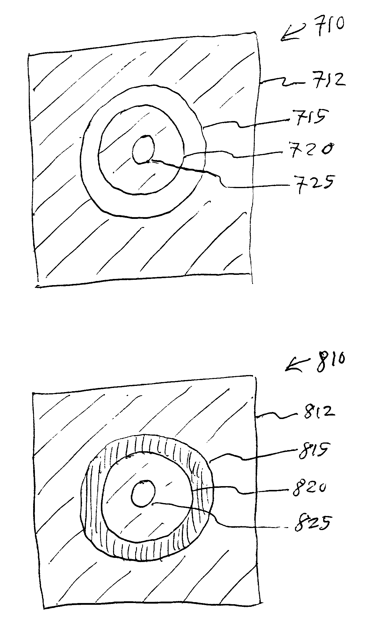
[0035] In the present invention, as shown in FIG. 3 (b), lithographic performance may be maximized by modulating or attenuating the intensity profile of the added illumination with respect to the intensity of the OAI. For example, a filter may be used in a further modified annular aperture 810 to reduce the intensity of the light passing through the annular opening 815 with respect to the light passing through the central circular opening 825. Other techniques include, but are not limited to, the addition of extra optics in the imaging system. For example, optical elements may be used to shape the illumination into an annulus and a central disk.

third embodiment

[0036] In the present invention, as shown in FIG. 4 (a), the center of a quadrupole aperture has been unblocked so as to include all or part of the type 2 illumination to augment OAI. When a high lens NA setting is used, a portion of the type 1 illumination is also included. The modified quadrupole aperture 910 of the claimed invention may be considered as having an imaginary square 917 within an opaque plate 912 that has a circular opening 915 located at each corner of the imaginary square 917 and a central circular opening 925 located at the center of the imaginary square 917.

fourth embodiment

[0037] In the present invention, as shown in FIG. 4 (b), lithographic performance may be maximized by modulating or attenuating the intensity profile of the added illumination with respect to the intensity of the OAI. In one case, at least one of the off-axis components of the illumination beam may be modulated. For example, a filter may be used in a further modified quadrupole aperture 1010 to reduce the intensity of the light passing through the quadrupole openings 1015 with respect to the light passing through the central circular opening 1025. In another case, the on-axis component of the illumination beam may be modulated.

[0038] Other techniques include, but are not limited to, the addition of extra optics in the imaging system. For example, optical elements may be used to shape the illumination into quadrupoles and a central disk.

[0039] In other embodiments of the present invention, the central opening and the at least one peripheral opening may have different quantities, size...


PUM


Abstract

The present invention describes an aperture comprising an opaque plate with a central opening and at least one peripheral opening and a method for combining an on-axis component and at least one off-axis component of illumination light.

Description

[0001] 1. Field of the Invention[0002] The present invention relates to the field of semiconductor integrated circuit (IC) manufacturing, and more specifically, to improving process control of critical dimension (CD) in lithography.[0003] 2. Discussion of Related Art[0004] Photolithography is the process by which a pattern of features on a mask is transferred into a layer of photoresist on a wafer. A latent image is created in the photoresist by exposure to light energy in an imaging tool. Subsequently, a develop process selectively removes portions of the photoresist layer which correspond to the latent image. The pattern realized in the photoresist is then replicated through an etch process into the wafer.[0005] The yield of microprocessors fabricated on a wafer is affected by the variability in CD of the printed features. CD is influenced by a variety of systematic and random factors. One type of effect derives from the interaction of photolithography with topography, film thickn...

Claims


Application Information

Patent Timeline
IPC IPC(8): G02B5/00G03F7/20
CPCG03F7/70091G02B5/005
Inventor LEE, THOMAS D.
Owner INTEL CORP
Why Eureka
Try Eureka