Fixing apparatus for ball lens

a technology for fixing apparatus and ball lens, which is applied in the direction of mechanical equipment, instruments, machine supports, etc., can solve the problems of difficult control of accuracy, difficult to achieve the effect of processing steps, and avoiding structural flaws in products caused by positioning errors of pads or o-rings

Inactive Publication Date: 2015-04-09
ATOMIC ENERGY COUNCIL INST O NUCLEAR ENERGY RES
View PDF5 Cites 13 Cited by
  • Summary
  • Abstract
  • Description
  • Claims
  • Application Information

AI Technical Summary

Benefits of technology

[0009]An objective of the present invention is to provide a fixing apparatus for ball lens, which is exempt from installation of supporting devices such as pads or O-rings one by one when a user is installing the ball lenses of a concentrator solar cell receiver module. Hence, the processing steps are reduced substantially. The installation of fixing apparatuses for ball lens to a power generating array with a great amount of solar cells can be finished at a time. Thereby, the operating efficiency is enhanced. In addition, the structural flaws in products caused by positioning errors of pads or O-rings can be avoided.
[0010]Another objective of the present invention is to provide a fixing apparatus for ball lens. In addition to improving the processing efficiency, the circuit board of the concentrator solar cell receiver module is also sheltered and protected. Thereby, damages and burnout of the circuit board due to off-axis illumination can be prevented.
[0011]For achieving the objectives described above, the present invention discloses a fixing apparatus for ball lens used for fixing at least a ball lens of a concentrator solar cell receiver module. The structure of the fixing apparatus comprises a plate and at least a fixing recess. The plate has a plurality of supporting legs underneath. The fixing recess is disposed on the surface of the plate and has a gap part at its bottom and penetrating the plate. The diameter or the longest diagonal of the gap part is shorter than the diameter of the ball lens. Besides, the ball lens contacts the top of an inner edge of the gap part. According to the design of the structure, after the solar cell receiver is placed on the substrate, the circuit intolerable of high temperature can be protected from burnout due to off-axis illumination of sunlight. In addition, the installation speed and quality of ball lens are improved significantly.

Problems solved by technology

Nonetheless, the current fixing method for ball lens is relatively difficult and complicated.
According to the structure according to the prior art as shown in FIG. 1, the whole process of installing the ball lens 5 is quite complicated and the accuracy is difficult to be controlled.
Thereby, if the pads 8 should be installed to each of the concentrator solar cell receiver modules one by one, the overall installation process, no matter manually or automatically, will consume substantial time and resources.
In addition, it is unavoidable that the locations of the pads 8 are deviated and thus influencing the focusing effect of the ball lenses.
The problem of this technology is, just like using the pads 8, that the concerns of complicated installation and deviation in locations still exist.
Another important issue of the prior art is that when the sunlight is off-axis, the focused light by the concentrating lens 65 may not be concentrated at the ball lens 5; it may illuminate directly on other devices, such as the conductive circuit 62, of the concentrator solar cell receiver module.

Method used


Image

  • Fixing apparatus for ball lens
  • Fixing apparatus for ball lens
  • Fixing apparatus for ball lens

Examples


Embodiment Construction

[0022]In order to make the structure and characteristics as well as the effectiveness of the present invention to be further understood and recognized, the detailed description of the present invention is provided as follows along with embodiments and accompanying figures.

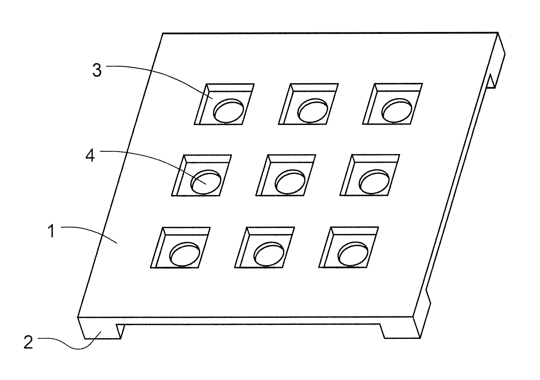
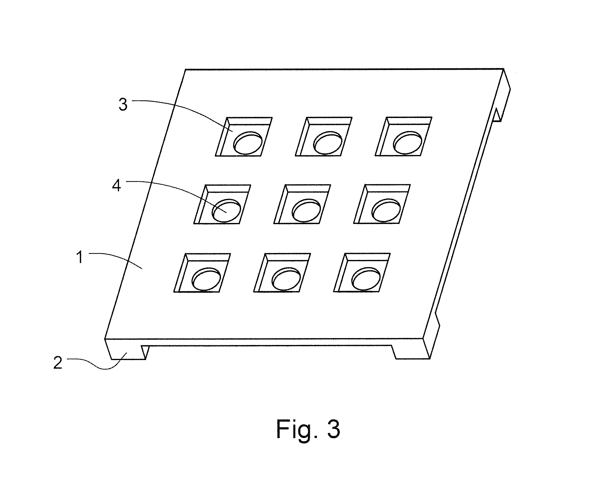
[0023]First, please refer to FIG. 3, which discloses the appearance of the structure according to the present invention. The present invention mainly comprises a plate 1, a plurality of supporting legs 2, a plurality of fixing recesses 3, and a plurality of gap parts 4. The plurality of supporting legs 2 are disposed under the plate 1. The plurality of fixing recesses 3 are located on the surface of the plate 1. At minimum, only one recess can be disposed. Moreover, the plurality of gap parts 4 are located at the bottom of the plurality of fixing recesses 3 and penetrating the plate 1.

[0024]In the structure according to the present invention, the plate 1 is used for providing support and positioning the bulk of the...


PUM


Abstract

The present invention relates to a fixing apparatus for ball lens used for facilitating installation of concentrator solar cell receiver module. The present invention can finish installing the fixing base for ball lens at a time and positioning the ball lens rapidly and accurately. It can also control the distance between the ball lens and the solar cell excellently. In addition, the present invention further has the function of sheltering the circuit of concentrator solar cell receiver module. When off-axis illumination of sunlight occurs, direct illumination of sunlight on, and consequently high-temperature burnout of, the circuit can be avoided. Thereby, the lifetime of the circuit can be extended effectively and the probability of failure can be reduced as well.

Description

FIELD OF THE INVENTION[0001]The present invention relates generally to a fixing apparatus for ball lens, and particularly to a fixing apparatus for ball lens used for improving the assembly efficiency and accuracy of a concentrator solar cell receiver module as well as protecting its circuit from burnout due to the off-axis illumination of sunlight.BACKGROUND OF THE INVENTION[0002]The most basic operational method of solar power generation is to illuminate sunlight on the surface of solar cells. Currently, there is a concentrator solar cell receiver module, which uses a concentrating lens to concentrate more photo energy for enhancing power generating efficiency. These concentrator solar cell receiver modules shrink the size of solar cells by increasing the concentrating multiple and using automatic production. Consequently, the costs of the materials for solar cells can be saved.[0003]In practice, small-area solar cells need to use secondary optical devices such as ball lenses for ...

Claims


Application Information

Patent Timeline
Patent Type & Authority Applications(United States)
IPC IPC(8): G02B7/02H02S40/22F16M11/22
CPCG02B7/027H02S40/22F16M11/22G02B7/021Y02E10/52H01L31/0543
Inventor LEE, YUEH-MUSHIH, ZUN-HAOLIANG, YI-PINGSHIN, HWA-YUHHONG, HWEN-FEN
Owner ATOMIC ENERGY COUNCIL INST O NUCLEAR ENERGY RES
Why Eureka
Try Eureka