Ic card handling device

Inactive Publication Date: 2002-10-24
ANRITSU CORP
View PDF0 Cites 10 Cited by
  • Summary
  • Abstract
  • Description
  • Claims
  • Application Information

AI Technical Summary

Benefits of technology

0045] An object of the present invention has been carried out in view of the points at issue and it is the object of the present invention to provide an IC card processor wherein there is no damage of a contact due to

Problems solved by technology

Further, since a uniform load is not applied on each terminal of the contact point group, there arises a trouble that each terminal is one-sidedly worn.
On the other hand, such an IC card processor is often used in the equipment such a public telephone used by an unspecified person, and frequently suffers damage from mischief such as insertion of a foreign matter.
Furthermo

Method used


Image

  • Ic card handling device
  • Ic card handling device
  • Ic card handling device

Examples


first embodiment

[0134] (First Embodiment)

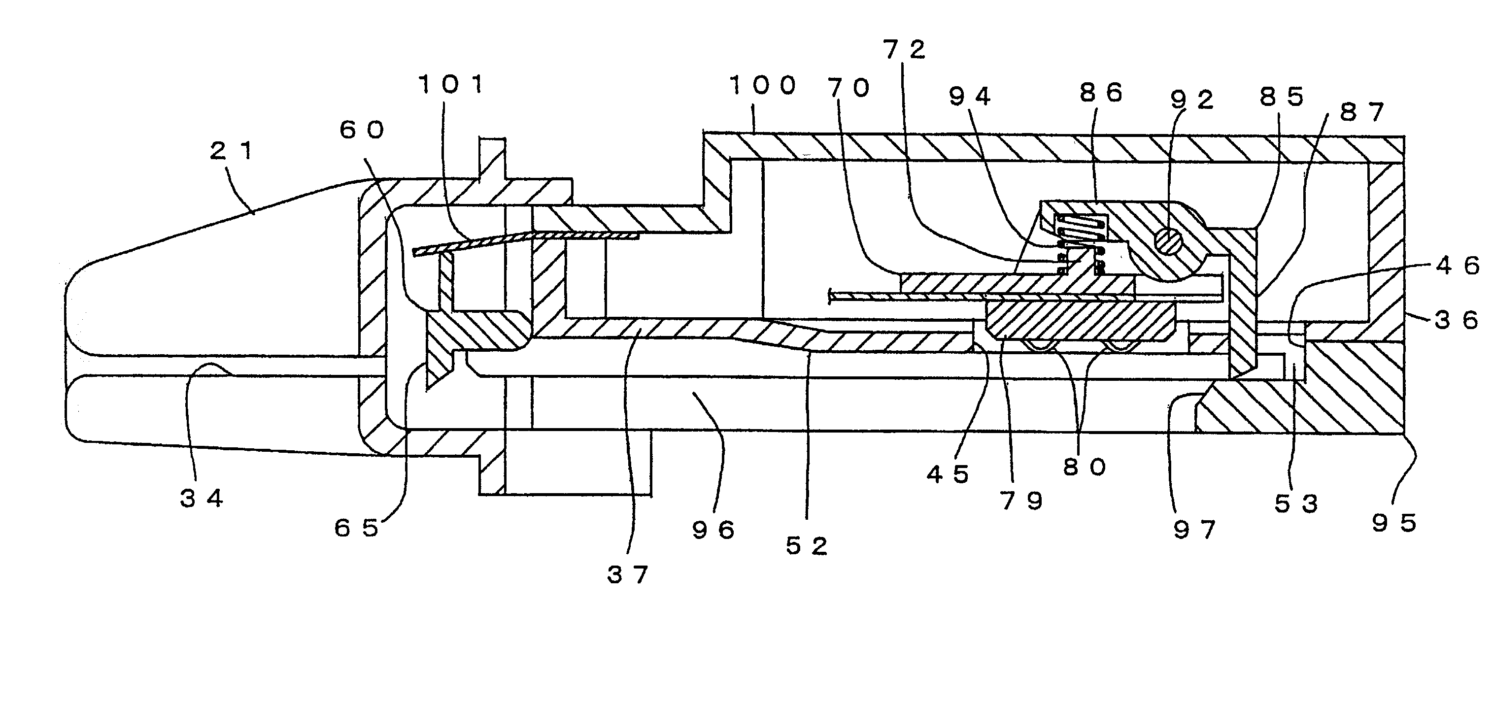
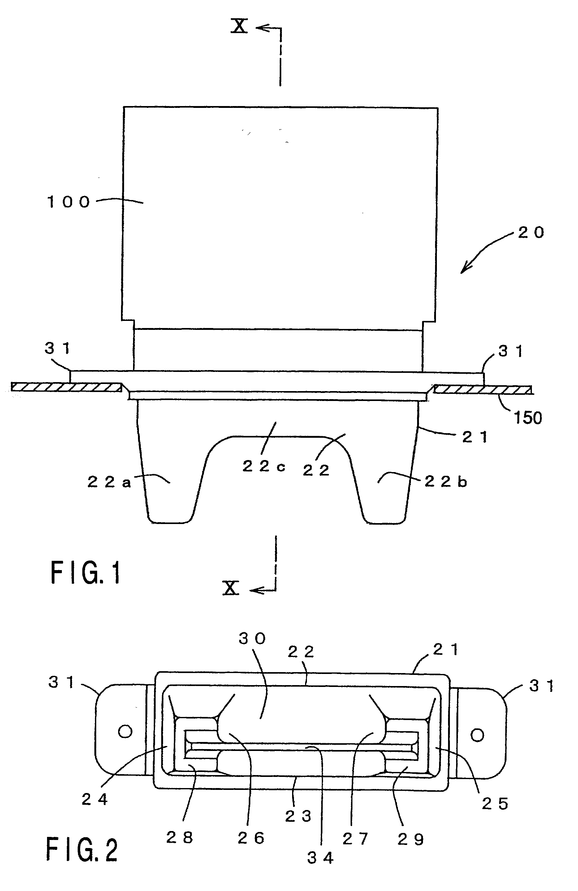
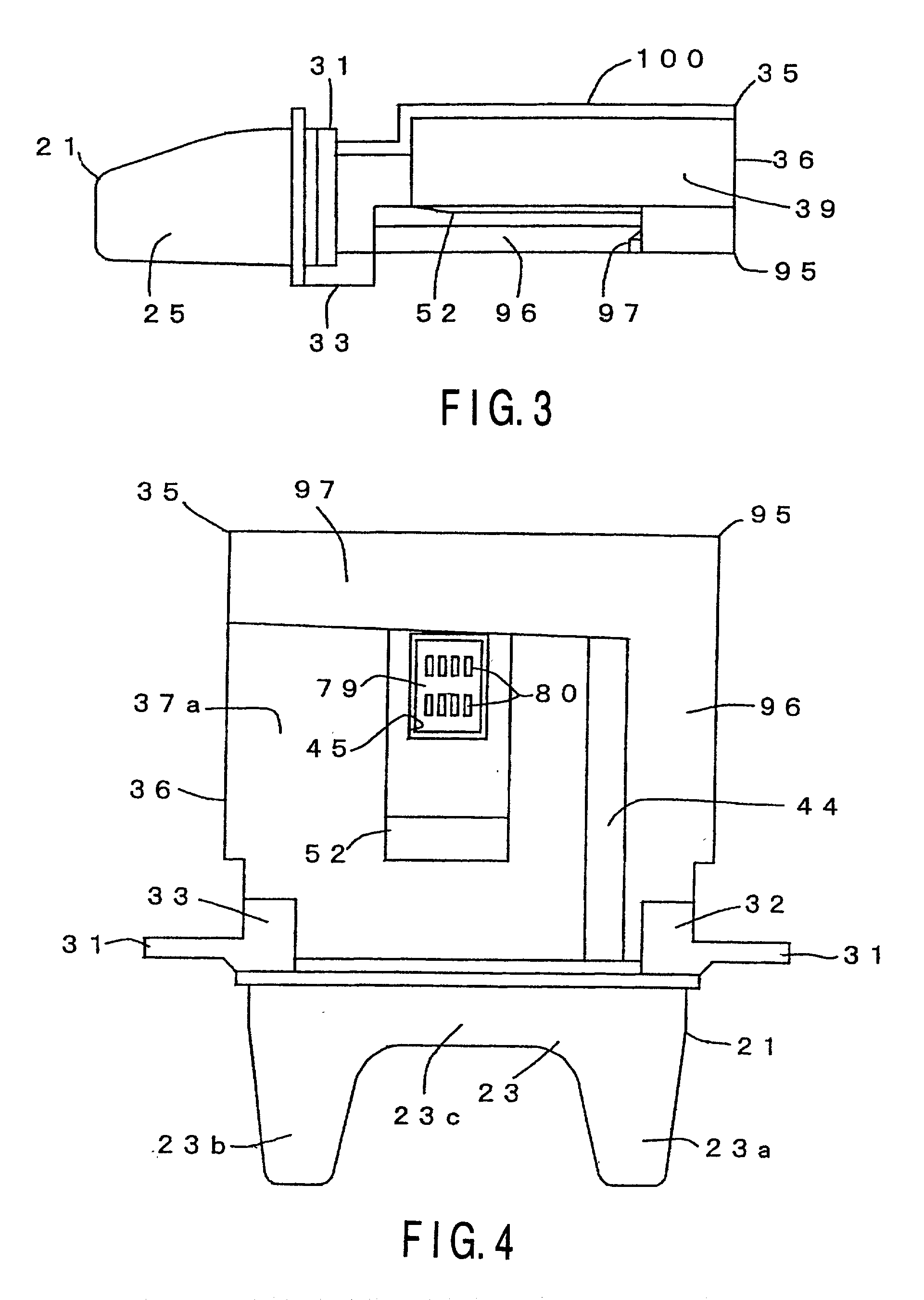
[0135] FIGS. 1 to 11 show a constitution of an IC card processor 20 and the essential portion thereof according to a first embodiment adopting the present invention.

[0136] This IC card processor 20 is constituted by a card slot 21 and a processor main body 35 as shown in FIGS. 1 to 4.

[0137] The card slot 21 is attached to the surface of a casing 150 of the equipment (for example, a public telephone) using an IC card and guides the IC card into the inside of a processor main body 35.

[0138] The card slot 21 has an upper plate 22 and a lower plate 23 which vertically oppose to each other, side plates 24, 25, 26, 27 covering a space between both side edges of right and left projecting portions 22a, 22b of the upper plate 22 and both sides edges of right and left projecting portions 23a, 23b of the under plate 23, respectively, front plates 28, 29 covering a space between the front edge of the right and left projecting portions 22a, 22b of the upper plate 22 and ...

second embodiment

[0224] (Second Embodiment)

[0225] An IC card processor 20 according to a second embodiment adopting the present invention and a constitution of the essential portion thereof and its basic action are the same as the IC card processor 20 according to the first embodiment adopting the present invention as shown in the FIGS. 1 to 16 and the essential portion thereof and its basic action.

[0226] Accordingly, here, an action characteristic to the IC card processor 20 according to the second embodiment will be described.

[0227] That is, as shown in FIG. 24, when the IC card 1 is inserted in a state where the card-like foreign matter having a short length is in a position with its rear end slightly beyond the slit 34, the foreign matter 2 advances into the inner part with its rear end pushed by the IC card, and when its rear end passes through the front end of the substrate 37, the one edge portion 2b descends.

[0228] For this reason, as shown in FIG. 25, the foreign matter 2 has one end side o...

third embodiment

[0252] (Third Embodiment)

[0253] An IC card processor 20 according to a third embodiment adopting the present invention and a constitution of the essential portion thereof and its basic action are the same as the IC card processor 20 according to the first and second embodiments adopting the present invention as shown in the FIGS. 1 to 16 and FIGS. 24 to 30 and the essential portions thereof and their basic actions.

[0254] Accordingly, here, an action characteristic to the IC card processor 20 according to the third embodiment will be described.

[0255] That is, as shown in FIG. 31, even when the IC card 1 is inserted in a state where the foreign matter 2 is inserted to a predetermined position by whatever method it is and the contact 80 contacts the foreign matter 2, by strongly pushing the IC card as shown in FIG. 32, its one edge portion la side superposes on the edge portion 2 of the foreign matter 2 so as to enter between the rail portion 97 and the escaping groove 44, and its top ...


PUM


Abstract

A card slot defines a space for receiving an IC card. A contact block has a plurality of contacts on one surface for contacting a plurality of contact points, respectively which are provided on one surface side of the IC cared received inside the card slot. A supporting mechanism movably supports the contact block in the vertical direction to the one surface of the IC card received inside the card slot, swingingly around a first axis line which passes through the center of the plurality of contacts of the contact block in the inserting direction of the IC card, and swingingly around a second axis line which passes through the center of the plurality of contacts of the contact block in the inserting direction of the IC card. An elastic member abuts against the contact block at one point only and applies a force to press the plurality of contacts of the contact block against one surface side of the IC card. A point of the place to which the pressing force is applied by the elastic member exists on an axis line which passes a cross point between the first axis line and the second axis line and extends vertically.

Description

[0001] The present invention relates to an IC card processor, and in particular, to an IC card processor having a contact block provided with a plurality of contacts on one surface side and allowing each contact of the contact block to contact each contact point of one surface side of an IC card received to a predetermined position so as to perform the giving / receiving of signals to / from the IC card, which adopts a technology that prevents damage of the contact due to insertion of an illegal card-like foreign matter.[0002] Further, the present invention relates to an IC card processor, and in particular to an IC card processor allowing each contact to contact each contact point of one surface side of an IC card received to a predetermined position so as to perform the giving / receiving of signals to / from the IC card, which adopts a technology that can easily eliminate a short card-like foreign matter existing inside.[0003] Conventionally, an IC card processor performing read / write of...

Claims


Application Information

Patent Timeline
IPC IPC(8): G06K7/00G06K13/08H01R13/24H01R13/629
CPCG06K7/0021G06K7/0026H01R13/629H01R13/2421G06K13/08
Inventor NAKAMURA, KATSUSHIIGUCHI, NOBUHIROFUJIMOTO, OSAMU
Owner ANRITSU CORP
Why Eureka
Try Eureka