Device approximating a shunt capacitor for strip-line-type circuits

a technology of strip-line-type circuits and devices, applied in the direction of resonators, basic electric elements, waveguides, etc., can solve the problems of significant limitations on layout flexibility and minimum circuit sizes

Inactive Publication Date: 2002-10-31
SUPERCONDUCTOR TECHNOLOGIES INC
View PDF0 Cites 21 Cited by
  • Summary
  • Abstract
  • Description
  • Claims
  • Application Information

AI Technical Summary

Problems solved by technology

Use of conductive patch shunt capacitors thus places significan...

Method used


Image

  • Device approximating a shunt capacitor for strip-line-type circuits
  • Device approximating a shunt capacitor for strip-line-type circuits
  • Device approximating a shunt capacitor for strip-line-type circuits

Examples


Embodiment Construction

[0028] Illustrative embodiments of the invention are described below. In the interest of clarity, not all features of an actual implementation are described in this specification. It will of course be appreciated that in the development of any such actual embodiment, numerous implementation-specific decisions must be made to achieve the developers' specific goals, such as compliance with system-related and business-related constraints, which will vary from one implementation to another. Moreover, it will be appreciated that such a development effort might be complex and time-consuming, but would nonetheless be a routine undertaking for those of ordinary skill in the art having the benefit of this disclosure.

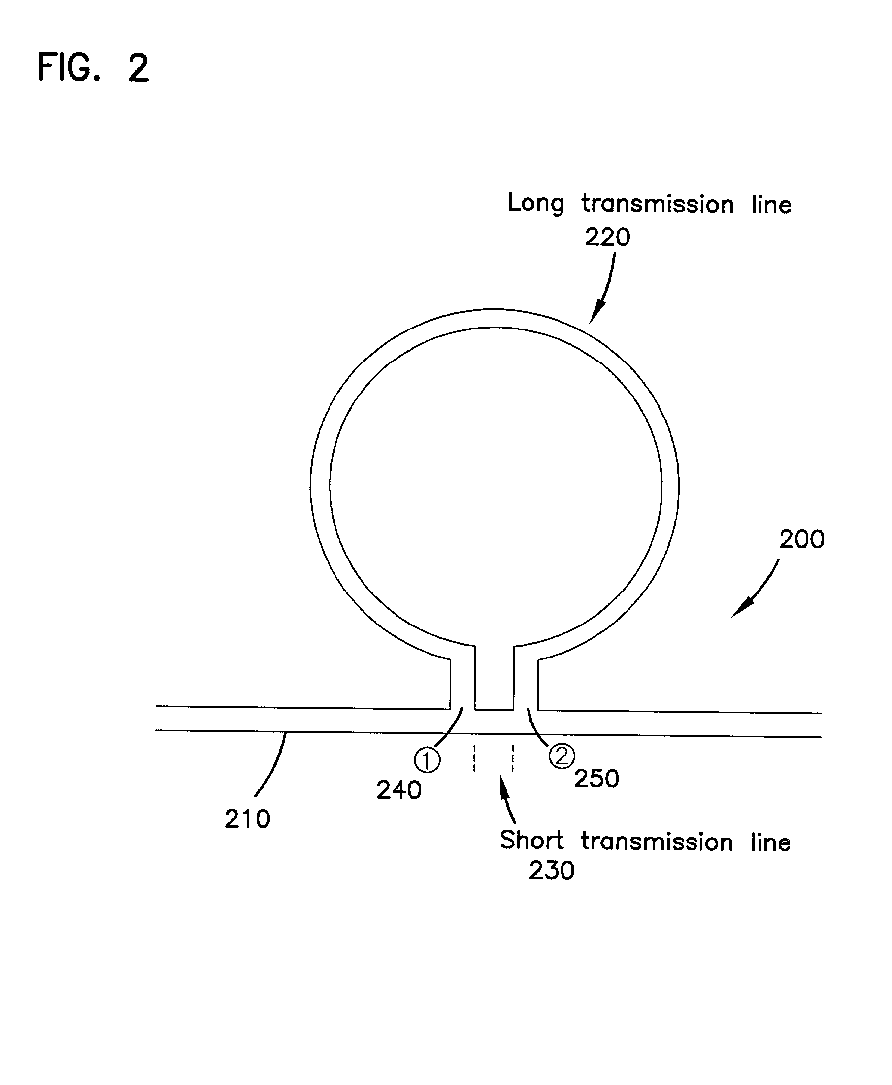
[0029] Referring to FIG. 2, one of the simplest embodiments of the invention is a circuit that includes a shunt capacitor realized by a closed conductive loop 200 and a transmission line 210 attached to the loop 200. The transmission line 210 in this case is connected to the loop...


PUM


Abstract

A closed conductive loop for use in planar circuits to realize shunt capacitors instead of conductive patches is disclosed. The closed conductive loop may be formed on a planar substrate or extend to multiple conductive layers in a multi-layer circuit. The use of closed conductive loops as shunt capacitors offers possibilities of more flexible circuit layout, reduced circuit footprint and comparable or improved performance as compared to using conductive patches as shunt capacitors.

Description

[0001] 1. Field of the Invention[0002] The present invention relates generally to strip-line-type circuits, more particularly to loop transmission lines as shunt capacitors used in such circuits.[0003] 2. Description of the Related Art[0004] Capacitors are one of the basic building blocks for electronic and microwave circuits. In microwave engineering, strip-line-type circuits, including microstrip, strip-line, and multi-layer circuits, can use large metal conductor patches to approximate shunt capacitors. Such patch capacitors can be found, for example, in bias networks of amplifiers, microstrip low pass filters, and matching networks.[0005] As with parallel plate capacitors, the capacitance realized from conductive patches on a microstrip circuit is directly proportional to the area of the patches and the dielectric constant of the substrate. Examples of microstrip patch capacitors are shown in FIG. 1. These patch capacitors can occupy a significant amount of surface area, dependi...

Claims


Application Information

Patent Timeline
IPC IPC(8): H01P1/203
CPCH01P1/20381H01P1/2039Y10S505/701Y10S505/866Y10S505/70
Inventor YE, SHEN
Owner SUPERCONDUCTOR TECHNOLOGIES INC
Why Eureka
Try Eureka