Touch switch layout and method for the control of a touch switch

Inactive Publication Date: 2002-11-07
E G O ELEKTRO GERAETEBAU GMBH
View PDF5 Cites 21 Cited by
  • Summary
  • Abstract
  • Description
  • Claims
  • Application Information

AI Technical Summary

Benefits of technology

[0010] It is fundamentally possible with the display means to display the state of several or all the loads. Since preferably for ease of operation in each case only the state of one load is simultaneously displayed, a state display of the loads should take place in alternating manner. Thus, it is a major advantage of the invention that for several loads only a single display means has to be provided and that the costs for further display means are saved. This expenditure saving is considerable, because it is not only possible to economize on the components per se, but also on their fitting and possible control. It also makes it possible to keep the printed circuit boards carrying the layouts smaller and simpler.

Problems solved by technology

This means that three touch switches are required for each electric load, which is very complicated, also from the standpoint of the control method.

Method used


Image

  • Touch switch layout and method for the control of a touch switch
  • Touch switch layout and method for the control of a touch switch
  • Touch switch layout and method for the control of a touch switch

Examples


Embodiment Construction

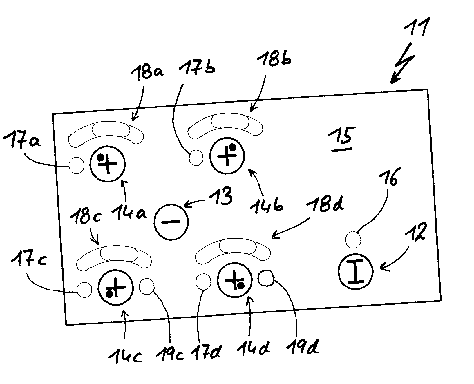
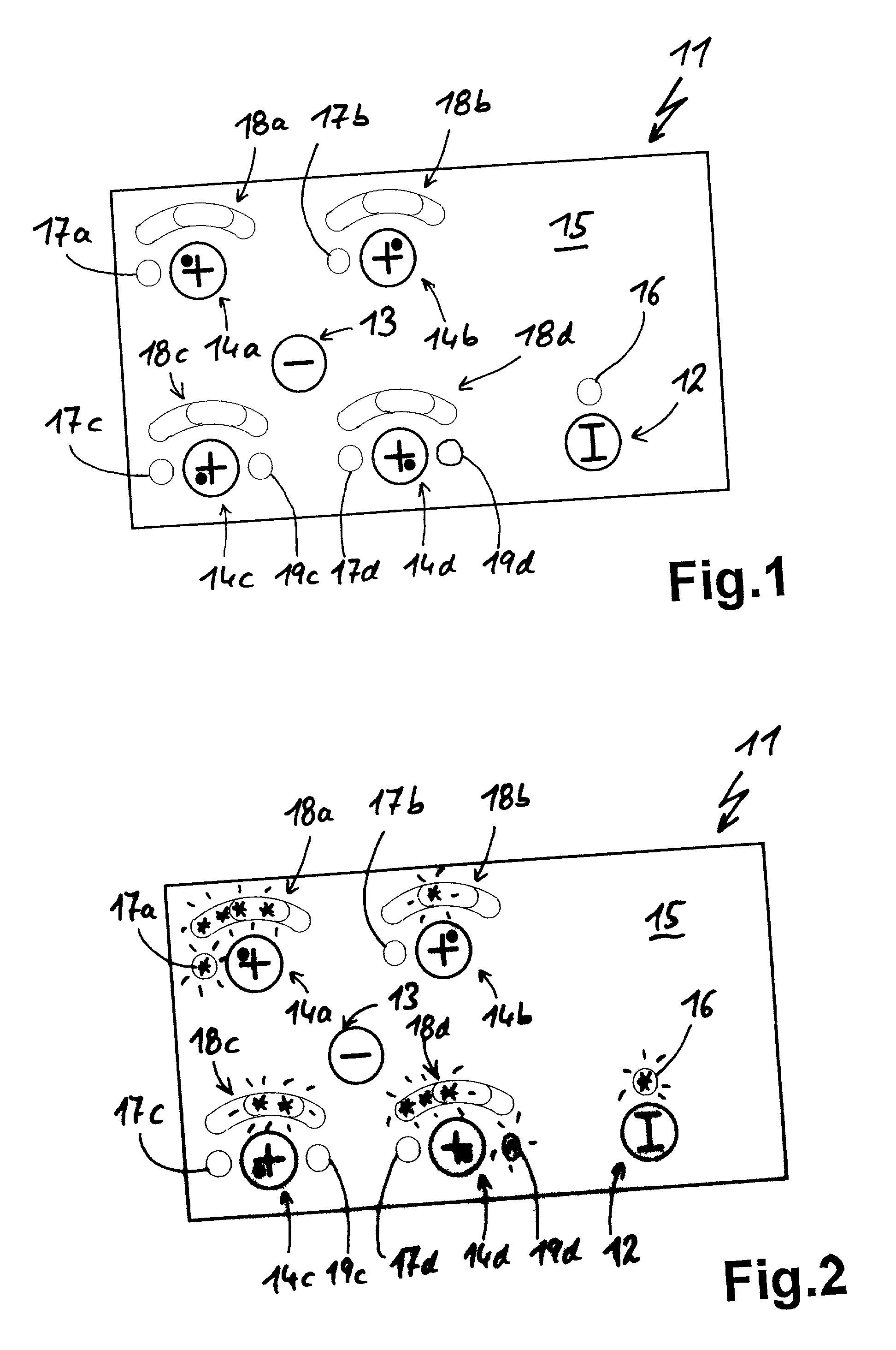
[0027] FIG. 1 shows a touch switch layout 11, which is shown in the operated state in FIG. 2. It has several touch switches, namely an on-off switch 12, a central minus or negative switch 13 and four selection / plus or positive switches 14a-d grouped around the negative switch 13. The individual touch switches 12 to 14a-d are represented by corresponding, imprinted decoration on the top of a contact or touch surface 15. In exemplified manner this is provided in an area of the glass ceramic hob, which is provided with imprints. These selection and positive switches 14a-d represent the four hot points of the hob, which is shown by the dot relative to the cross or plus sign.

[0028] An on-off switch 12 has an activatable LED 16, which lights up when the hob is switched on. No display is associated with the central negative switch 13. Display means in the form of a selection LED 17a-d and bar LED displays 18a-d arranged in circular arc form are associated with the individual selection swit...


PUM


Abstract

A touch switch layout for a hob having several hotplates is described. For said hotplates is in each case provided a separate selection switch with which the power can be selected in each case. There is also a single, common touch switch for power reduction for all the hotplates. According to the associated operating method, on operating the common power control switch only the power of a selected hotplate is modified or reduced. The power of a hotplate is increased by briefly operating a selection button as selection and renewed operation of the selection button as an increase. This then functions as a power increase switch. It is obvious that the function can also be reversed.

Description

FIELD OF APPLICATION AND PRIOR ART[0001] The invention relates to a touch switch layout according to the preamble of claim 1. The invention also relates to a method according to the preamble of claim 20. Such touch switch layouts are advantageously used for electrical appliances having several electric loads. The electric loads can be adjusted with regards to their electric power. By means of a selection switch, they can be selected for a power setting or control to be performed.[0002] Such known touch switch layouts have a selection switch for each electric load, as well as a positive and minus button for the power setting. This means that three touch switches are required for each electric load, which is very complicated, also from the standpoint of the control method.PROBLEM AND SOLUTION[0003] The problem of the invention is to provide a touch switch layout and a control method for electrical appliances having several electric loads, which can be manufactured with less effort and...

Claims


Application Information

Patent Timeline
Patent Type & Authority Applications(United States)
IPC IPC(8): A47J37/06F24C15/00F24C7/08H01H9/16H03K17/96H05B3/74
CPCH05B3/746F24C7/082
Inventor GREMM, OLIVERHERWEG, ELMAR
Owner E G O ELEKTRO GERAETEBAU GMBH
Why Eureka
Try Eureka