Fluid conduits and method of manufacturing same

Inactive Publication Date: 2002-11-14
INNATECH
View PDF14 Cites 13 Cited by
  • Summary
  • Abstract
  • Description
  • Claims
  • Application Information

AI Technical Summary

Benefits of technology

[0009] In order to address these needs, the present invention contemplates a flexible configurable conduit that is produced using an over-molding process. In one embodiment of the invention, a flexible conduit is provided that comprises a plurality of like-configured components or links, each of the components including a male member at one end and a female member at another end, and a passageway extending between the male member and the female member. The components are formed in a molding process, such as a plastic injection molding process. In accordance with one aspect of the invention, the female member of one component is over-molded about a male member of an immediately adjacent component. The female component can be over-molded to surround a substantial portion of the male member, thereby significantly reducing the likelihood, or even ability, for the two components to be disassembled.
[0022] One benefit of the present invention is that is greatly simplifies the process for manufacturing a continuous length of flexible conduit. A further benefit is realized by features of the invention that allow product of a substantially fluid tight seal between articulating components of the flexible conduit.

Problems solved by technology

One detriment inherent with many of these prior approaches is that the articulating joint is not fluid-tight.
Thus, the prior ball-and-socket snap-fit devices are usually limited to low pressure applications or uses where a little fluid leakage does not pose a problem.
In some prior devices, the leakage problem is addressed by the inclusion of a seal ring or gasket to the ball-and-socket joint, which necessarily adds cost and complexity of production.
Even where the configurable conduit is not being used to carry a fluid, the prior devices suffer from the additional detriment of requiring piece-by-piece, or link-by-link, assembly.
Then the individual links are snapped together, usually manually, which makes production of any significant length of configurable flexible conduit unwieldy and expensive.
Another detriment of the flexible conduits mentioned above is that the links can be pulled apart, often more easily than when the links are snapped together.
Inadvertent and unexpected disassembly of the conduit can range from simply a nuisance, such as where the conduit is used to shield a cable, to a potential disaster, such as where the conduit is part of a home plumbing system.

Method used


Image

  • Fluid conduits and method of manufacturing same
  • Fluid conduits and method of manufacturing same
  • Fluid conduits and method of manufacturing same

Examples


Embodiment Construction

[0031] For the purposes of promoting an understanding of the principles of the invention, reference will now be made to the embodiments illustrated in the drawings and described in the following written specification. It is understood that no limitation to the scope of the invention is thereby intended. It is further understood that the present invention includes any alterations and modifications to the illustrated embodiments and includes further applications of the principles of the invention as would normally occur to one skilled in the art to which this invention pertains.

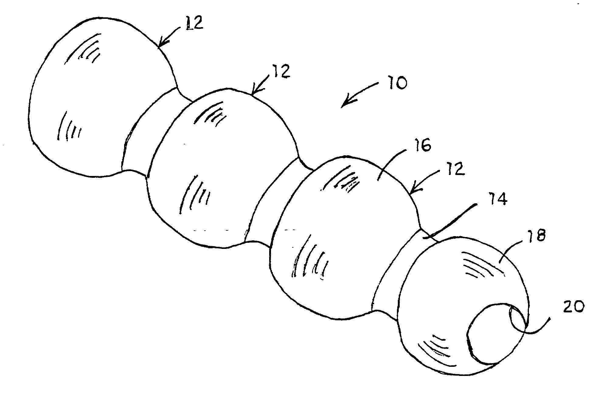
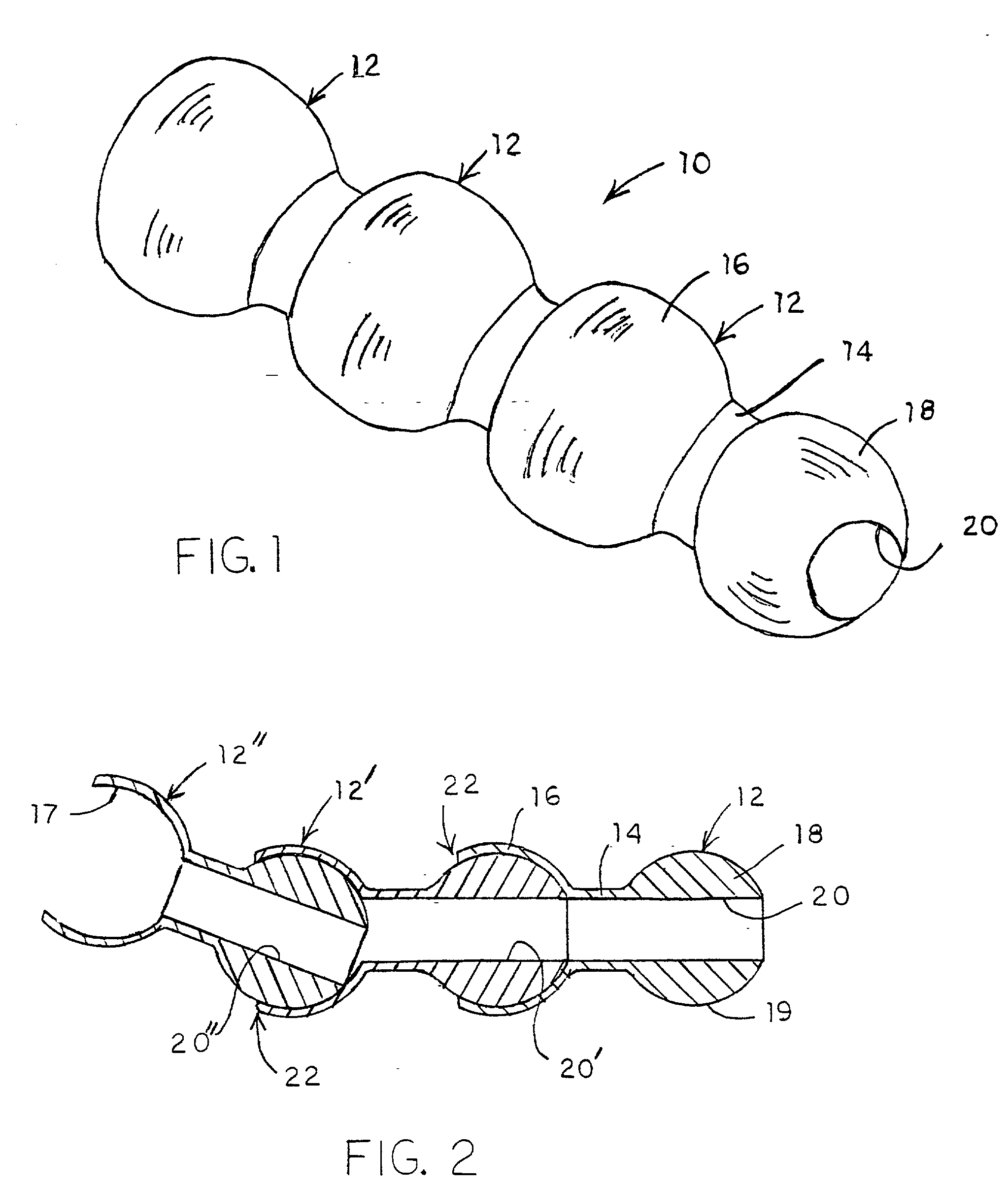
[0032] In accordance with one aspect of the invention, a continuous flexible conduit 10 includes a series of like-configured components or links 12, as shown in FIG. 1. For the purposes of the present disclosure, the conduit 10 is provided as a fluid conduit capable of conveying a pressurized fluid. Of course, it will be readily appreciated that this inventive flexible conduit can be utilized in a wide variety ...


PUM

PropertyMeasurementUnit
Temperatureaaaaaaaaaa
Lengthaaaaaaaaaa
Flexibilityaaaaaaaaaa

Abstract

A continuous flexible conduit is formed from like-configured components, each having a male joint member and a female joint member with a passageway extending therethrough. The female joint member is over-molded about a corresponding male joint member to form a substantially fluid-tight articulating joint. In a method of producing the flexible conduit, a single-shot molding process is used to form each like-configured component, with each newly formed component indexed within the single-shot mold so that the male joint member is within the female mold cavity for the formation of the next component. In an alternative embodiment, a continuous conduit is formed of two different sets of like configured components-one set having only female joint members and the other set having only male joint members. A two-shot molding process is described for continuous production of the flexible conduit using these two sets of components.

Description

Reference to Related Application[0001] This utility patent application claims priority to co-pending provisional application, Serial No. 60 / 287,520, entitled "Fluid Conduits and Valves and Method of Manufacturing Same", filed on Apr. 26, 2001, the disclosure and figures of which is incorporated herein by reference.Background of the Invention[0002] Flexible conduits, hoses and tubes are known in many fields. Flexible conduits are frequently used as part of a fluid system, the garden hose being a well-known example. One improvement to these known flexible conduits has been the inclusion of configurable joints along the length of the conduit. In a typical configurable conduit, a series of segments are joined at ball-and-socket joints. The friction between the ball element and socket element helps hold adjacent segments in a particular orientation. In addition, the close running fit between these elements ostensibly acts as a fluid sealing surface to minimize leakage.[0003] Configurable...

Claims


Application Information

Patent Timeline
IPC IPC(8): B29C45/00B65D5/74B65D47/30F16L11/18
CPCB29C45/0003B29C45/0017B29L2023/005F16L11/18B65D5/747B65D47/305B29L2031/22
Inventor ELDER, JACK E.
Owner INNATECH
Why Eureka
Try Eureka