Face portion detecting apparatus

a detection apparatus and face portion technology, applied in the field of face portion detection apparatus, can solve the problems of erroneous detection of reflection image 142 reflected from the surface of the spectacle lens, inability to correctly extract the eye portion, and certain probability

Inactive Publication Date: 2002-12-05
MITSUBISHI ELECTRIC CORP
View PDF8 Cites 41 Cited by
  • Summary
  • Abstract
  • Description
  • Claims
  • Application Information

AI Technical Summary

Problems solved by technology

In the above-explained detecting apparatus disclosed in Japanese Patent Laid-opens No. 06-270711 and No. 09-081756, however, in such a case that the human being wears spectacles, there are such possibilities that the eye portion cannot be correctly extracted due to the adverse influences caused by the reflection image, which occurs on the luster reflection surfaces of the spectacles.
As a result, there is a certain probability that the reflection image 142 reflected from the surface of the spectacle lens is erroneously detected as the retina reflection image.
However, this suppression effect cannot be achieved, depending upon the angles of the head portion.
Furthermore, in the detecting apparatus disclosed in Japanese Patent Laid-open No. 10-216234, since the human being must wear the specific spectacles, the human being feels cumbersome, which is a problem.

Method used


Image

  • Face portion detecting apparatus
  • Face portion detecting apparatus
  • Face portion detecting apparatus

Examples


embodiment 1

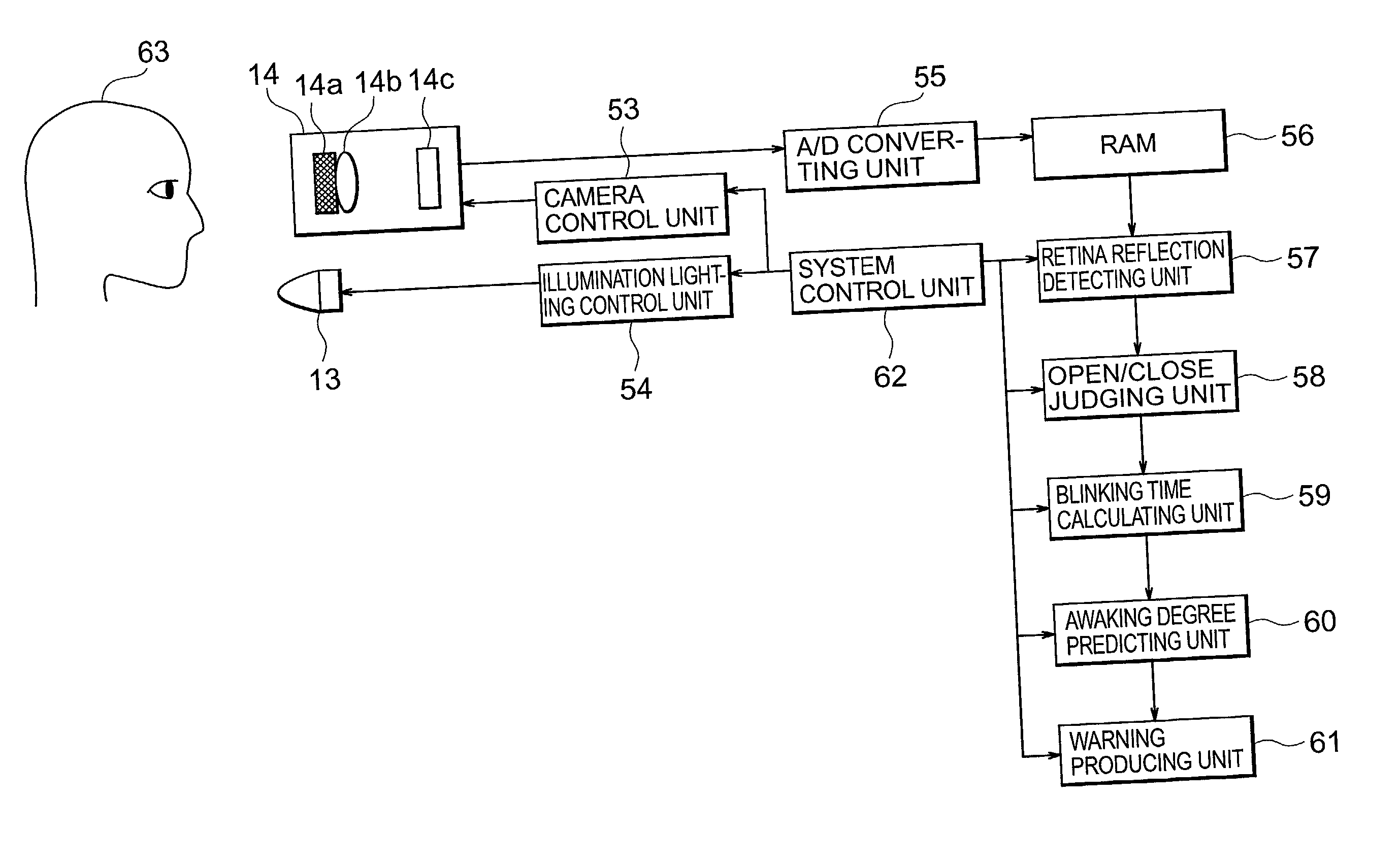
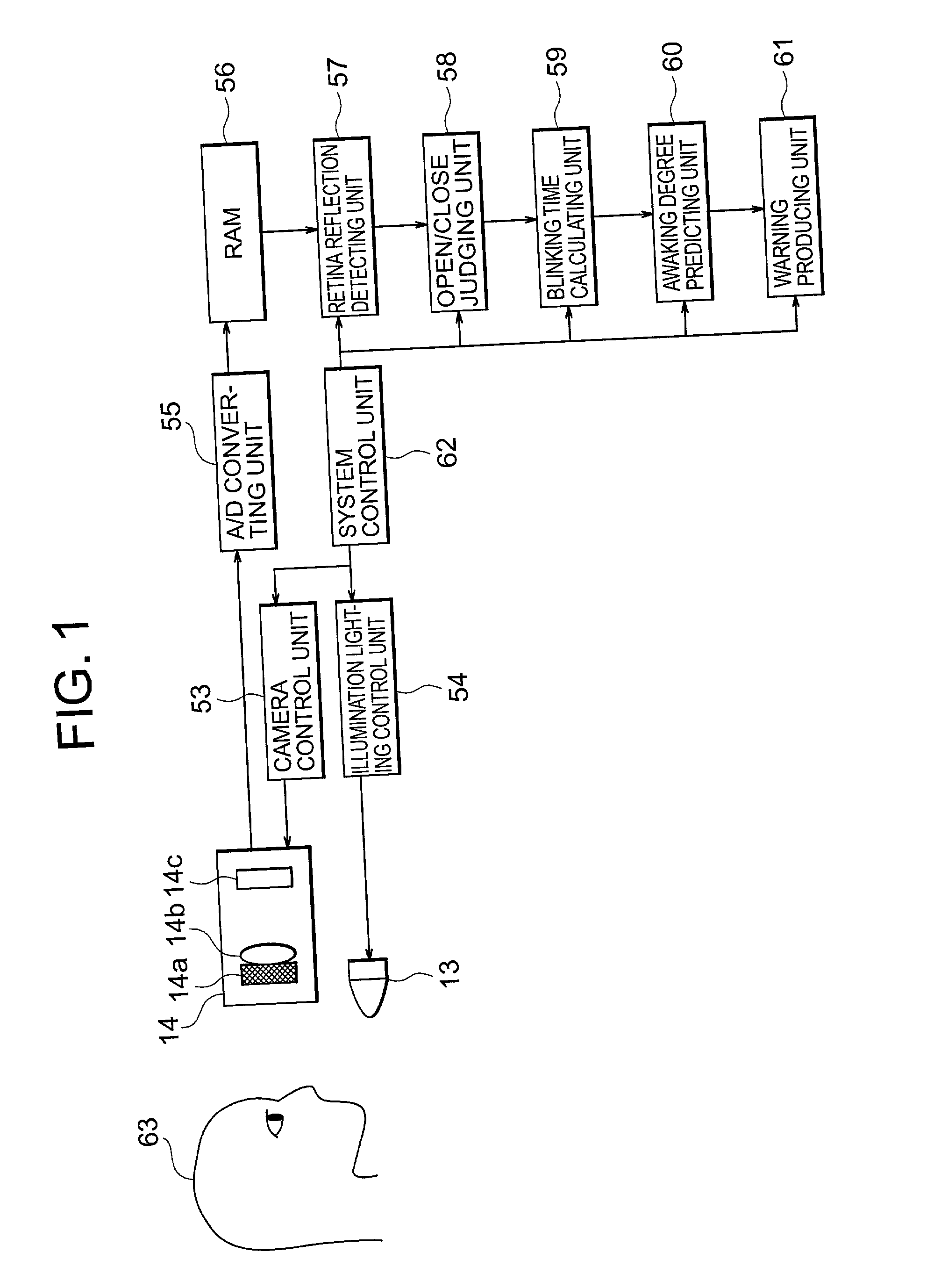
[0050] Also, in this drawing, reference numeral 55 indicates an A / D converting unit for A / D-converting an analog image signal outputted from the camera 14, reference numeral 56 represents an RAM (random access memory) for storing thereinto the digital image data obtained by A / D-converting the analog image signal, and reference numeral 57 represents a retina reflection detecting unit (face portion detecting means) for detecting a retina reflection image by using the image data stored in this RAM 56. Also, reference numeral 58 denotes an open / close judging unit for judging open / close states of pupils by using the retina reflection image detected by the retina reflection detecting unit 57, reference numeral 59 shows a blinking time calculating unit for calculating a blinking time duration based upon the pupil-open / close-state judgement, and reference numeral 60 shows an awaking degree predicting unit for predicting an awaking degree of a car driver (will be explained later) by processi...

embodiment 2

[0073] Referring now to drawings, a description will be made of a face portion detecting apparatus according to an embodiment 2 of the present invention. It should be understood that an overall arrangement of this face portion detecting apparatus according to the embodiment 2 is similar to that of the face portion detecting apparatus according to the above-explained embodiment 1.

[0074] FIG. 7 and FIG. 8 illustratively show contents of the second embodiment 2 of the present invention. In this embodiment 2, two or more illumination light sources 13 are arranged on a straight line as illustrated in FIG. 7.

[0075] In FIG. 8, reference numeral 17 indicates a reflection image reflected on the surface of the spectacle lens 12 photographed by the camera 14.

[0076] In the case of FIG. 7, while a single image is photographed by the camera 14, a plurality of these illumination light sources 13 are continuously turned ON in either a sequential manner or a random manner in synchronism with the pho...

embodiment 3

[0081] Referring now to drawings, a description will be made of a face portion detecting apparatus according to an embodiment 3 of the present invention. It should be understood that an overall arrangement of this face portion detecting apparatus according to the embodiment 3 is similar to that of the face portion detecting apparatus according to the above-explained embodiment 1.

[0082] The illumination light sources 13 are arranged in the straight line form in the above-described embodiment 2, whereas a plurality of light sources 13 are arranged in a coaxial form with respect to the optical axis of the camera 14 in this embodiment 3. Referring now to FIG. 9 and FIG. 10, this face portion detecting apparatus of the embodiment 3 will be described.

[0083] FIG. 9 is a diagram for illustratively indicating a plurality of illumination light sources 13 and a camera 14, as viewed from a car driver. In FIG. 9, a plurality of illumination light sources 13 are arranged in a coaxial form with re...


PUM


Abstract

In a face portion detecting apparatus, an image of an eye portion of a car driver can be properly extracted without adverse influences caused by a reflection image reflected from a luster reflection surface of spectacles worn by the car driver. The face portion detecting apparatus is arranged by a light source of an illumination for illuminating a face portion of a human being from different directions from each other; a camera for photographing the face portion which is illuminated by the light source; an illumination lighting control unit for controlling turn-ON operation of the light source; a camera control unit for controlling the camera in synchronism with the turn-ON operation of the illumination light source; and a retina reflection detecting unit for removing a reflection image of an article having a luster reflection surface by employing at least one image which is acquired by the camera in synchronism with the turn-ON operation of the illumination light source, whereby only a determined face portion is extracted.

Description

[0001] This application is based on Application No. 2001-162079, filed in Japan on May 30, 2001, the contents of which are hereby incorporated by reference.[0002] 1. Field of the Invention[0003] The present invention is related to a face portion detecting apparatus in which a human face portion is irradiated by light and a desirable face portion is detected while suppressing an adverse influence made by a reflection image caused by an article having a luster reflection surface such as spectacles (glasses).[0004] 2. Description of the Related Art[0005] Conventionally, various methods for detecting eye portions by using reflection images produced by irradiating near infrared rays have been widely utilized. For instance, Japanese Patent Laid-open No. 06-270711 discloses a method operated in such a manner that while the near infrared rays are irradiated to the human eyeball portion, the pupil region of the eyeball portion is detected, and then blinking actions are detected based upon th...

Claims


Application Information

Patent Timeline
Patent Type & Authority Applications(United States)
IPC IPC(8): A61B3/14G06T1/00B60K28/06G06V10/141
CPCG06K9/00255G06K9/2027G06K9/00604G06V40/166G06V40/19G06V10/141
Inventor ISHIKURA, HISASHI
Owner MITSUBISHI ELECTRIC CORP
Why Eureka
Try Eureka