Burner with exhaust gas recirculation

a burner and recirculation technology, applied in the direction of gaseous fuel burners, combustion types, lighting and heating apparatuses, etc., can solve the problems of diffuse-like combustion usually not being optimally carried out in terms of emissions, unstable flame, and complicated burner design for two different operating modes

Inactive Publication Date: 2002-12-12
ALSTOM TECH LTD
View PDF0 Cites 80 Cited by
  • Summary
  • Abstract
  • Description
  • Claims
  • Application Information

AI Technical Summary

Problems solved by technology

A principal problem which has to be solved within the framework of the development of industrial premixing burners for use in gas turbines or for hot-gas generation is the stabilization of the flame primarily in the part-load operating mode.
The problem with this, however, is that, on the one hand, it is complicated to design a burner for two different operating modes and, on the other hand, diffusion-like combustion usually cannot be carried out optimally i

Method used


Image

  • Burner with exhaust gas recirculation
  • Burner with exhaust gas recirculation
  • Burner with exhaust gas recirculation

Examples


Embodiment Construction

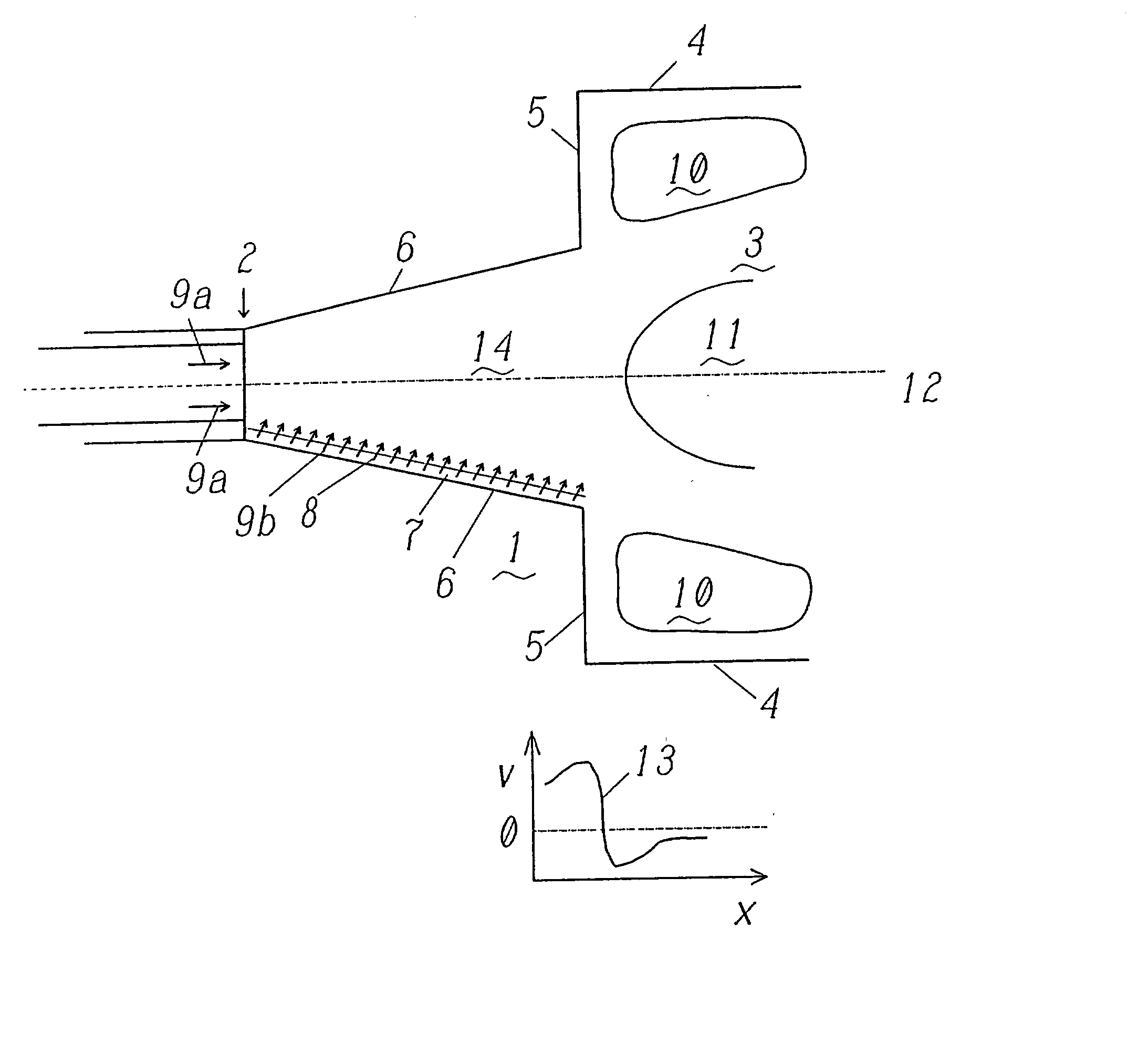
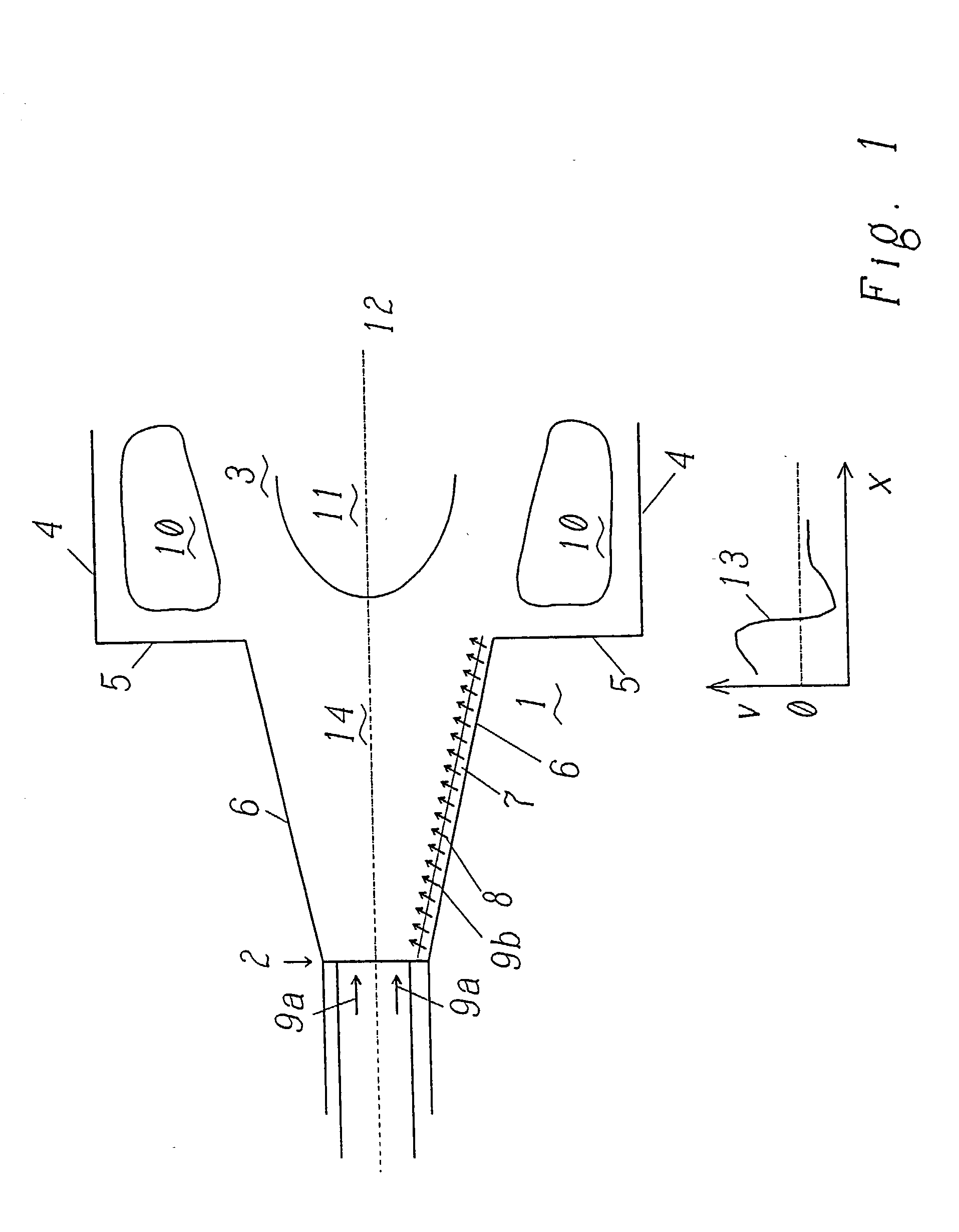
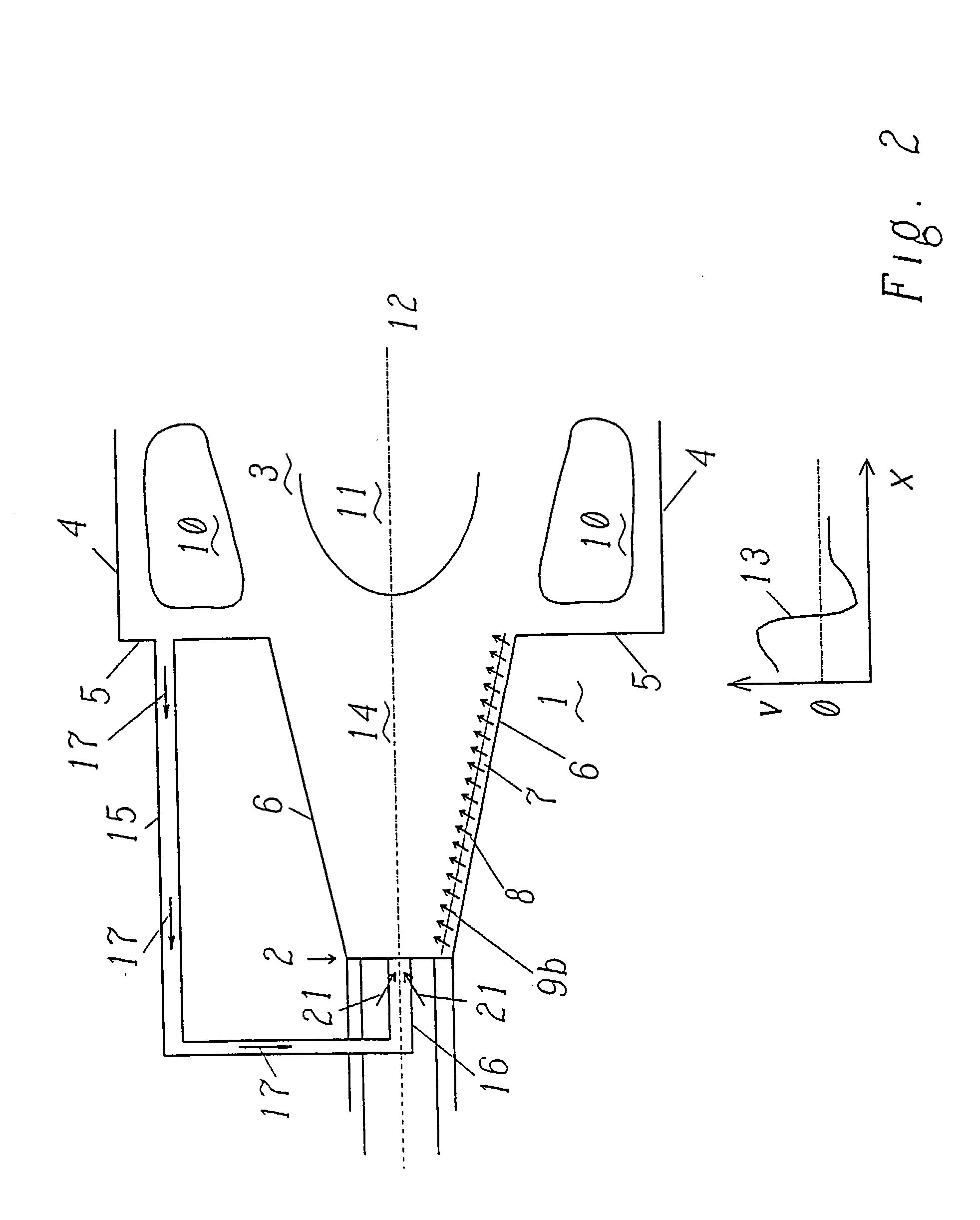
[0027] FIG. 1 shows a double-cone burner 1, formed from two part-cone bodies 6, the axes of which are offset relative to one another in such a way that a slot 7 is formed between the part-cone bodies 6. Combustion air 9b flows tangentially through this slot 7 into the burner interior 14. Moreover, axial combustion air 9a is supplied to the burner interior 14 from the side of the burner tip 2 where the diameter of the burner is at a minimum. Fuel 8 is admixed with the tangential combustion air 9b, so that a conical swirling cone consisting of a fuel / air mixture is formed in the burner interior 14. In addition to the admixing of fuel near the slot 7 between the part-cone bodies 6, in particular, liquid fuel can also be supplied to the burner interior 14 axially, that is to say near the burner tip 2, via a central nozzle.

[0028] During the outflow of this cone into the combustion chamber 3, various backflow zones are formed at the same time. On one side, what are known as outer backflow...


PUM


Abstract

In a premixing burner (1) for a gas turbine or hot-gas generation for the combustion of liquid or gaseous fuel, in which fuel is mixed with combustion air (9a, 9b) in a burner interior (14), is fed to a combustion chamber (3) and is burnt in this combustion chamber (3), stabilization in the part-load mode is achieved in a simple and efficient way in that means (15) are provided which make it possible to recirculate hot exhaust gas (17) out of the combustion chamber (3) into the burner interior (14) and to stabilize the flame by means of selfignition processes. The means (15) are preferably a recirculation line which picks up hot exhaust gas (17) from the outer backflow zone (10) and feeds it to the burner interior (14) in the region of a burner tip (2) facing away from the combustion chamber (3), additional fuel (pilot fuel 21) being admixed with the exhaust gas (17) in the recirculation line upstream of the feed to the burner interior (14).

Description

[0001] The present invention relates to a burner for a gas turbine or hot-gas generation for the combustion of liquid or gaseous fuel and to a method for operating it.PRIOR ART[0002] A principal problem which has to be solved within the framework of the development of industrial premixing burners for use in gas turbines or for hot-gas generation is the stabilization of the flame primarily in the part-load operating mode. Most industrial burners of this type utilize a swirl flow for generating a backflow zone on the burner axis. In these burners, flame stabilization takes place aerodynamically, that is to say without special flame holders. In this case, the backflow zones, which occur during the breakdown of the vortex, or the outer recirculation zones are utilized. Hot exhaust gases from these zones in this case ignite the fresh fuel / air mixture.[0003] A burner according to the prior art, in which, for example, a backflow zone of this type is formed on the axis of the burner, is des...

Claims


Application Information

Patent Timeline
IPC IPC(8): F23C7/00F23C9/00F23D11/40F23D17/00
CPCF23C7/002F23C9/00F23D17/002F23D11/402F23C2900/07002
Inventor DOEBBELING, KLAUSPAIKERT, BETTINAPASCHEREIT, CHRISTIAN OLIVER
Owner ALSTOM TECH LTD
Why Eureka
Try Eureka