
Method and device for connecting solar battery modules

a technology of solar cells and solar cells, applied in the direction of coupling device connections, semiconductor devices, electrical apparatus, etc., can solve the problems of easy miscounting and confusion of the number of connections required to join solar cells

Inactive Publication Date: 2002-12-19
SUMITOMO WIRING SYST LTD
View PDF0 Cites 24 Cited by
  • Summary
  • Abstract
  • Description
  • Claims
  • Application Information

AI Technical Summary

Benefits of technology

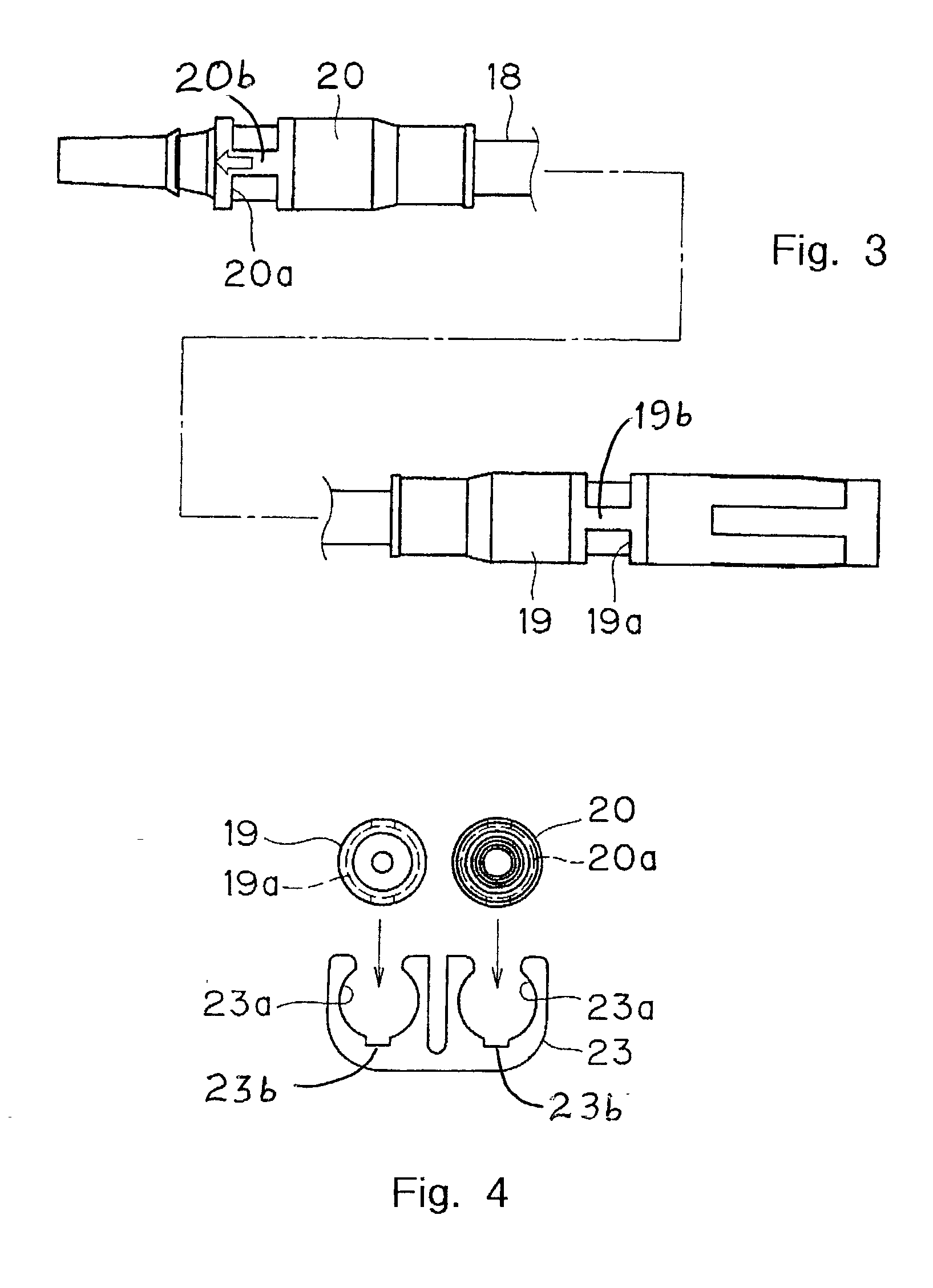
[0012] In another aspect of the present invention, a clamp is provided in combination with a pair of cables each having at least one connector for connecting to a solar battery module, each connector including at least one clamp groove. The clamp may include a pair of joint receptacles, each joint receptacle configured to receive a respective one of the connectors, and wherein each joint receptacle resiliently engages the clamp groove of a respective connector to maintain the connectors in a parallel arrangement and to prevent longitudinal displacement of the connectors relative to the clamp. Each connector may further include at least one rib positioned within the clamp groove, and the joint receptacles may further include a groove that receives the rib to thereby prevent rotation of the respective connector relative to the clamp.
[0014] According to yet another aspect of the present invention, a clamp is provided for connecting a pair of cables, each cable having at least one connector for connecting to a solar battery module, and each connector including at least one clamp groove and at least one rib positioned within the clamp groove. The clamp includes a pair of first joint receptacles, each first joint receptacle configured to receive a respective one of the connectors, and wherein each first joint receptacle resiliently engages the clamp groove of a respective connector to maintain the connectors in a parallel arrangement and to prevent longitudinal displacement of the connectors relative to the clamp. The first joint receptacles may further include a groove configured to receive the rib of a respective connector to thereby prevent rotation of the respective connector relative to the clamp.

Problems solved by technology

There is a problem associated with this connecting operation in that the number of connections required to join solar battery modules 11 can be easily miscounted and confused.

Method used


Image

  • Method and device for connecting solar battery modules
  • Method and device for connecting solar battery modules
  • Method and device for connecting solar battery modules

Examples


first embodiment

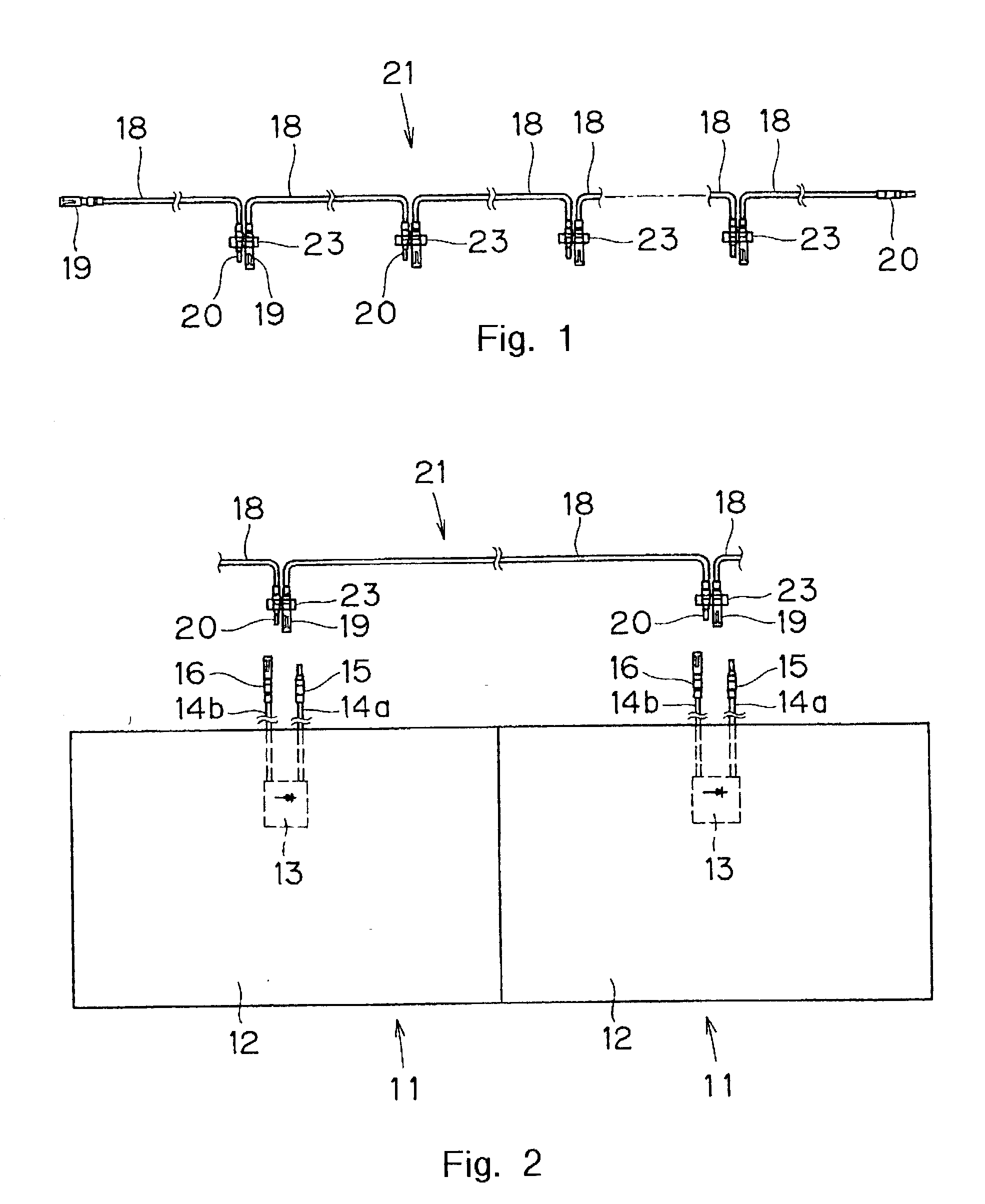
[0032] The following describes the present invention with reference to FIGS. 1 through 6. Similar to the structure of a conventional solar battery module, output cables 14a and 14b extend an appropriate length from terminal box 13 located on the rear surface of module body 12 of solar battery module 11. Male connector 15 and female connector 16 are attached to the extended ends of each cable 14a and 14b respectively.

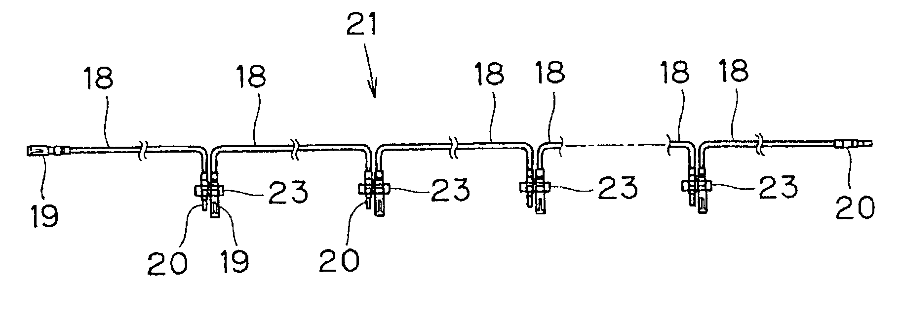
[0033] Relay cables 18 are provided at an appropriate length for connection to each solar battery module 11, one end of each relay cable 18 being equipped with female connector 19 that can be removably connected to male connector 15, and the other end with male connector 20 that can be removably connected to female connector 16.

[0034] When laying out and connecting each of a prescribed number of solar battery modules 11 in series, relay cable assembly 21 is first constructed by mutually joining, in series, a number of relay cables 18 that corresponds to the number of sol...

second embodiment

[0041] In this second embodiment, clamp 23 is used to maintain male connector 15 and female connector 16 as a connector pair, connectors 15 and 16 being respectively attached to the terminal ends of output cables 14a and 14b of solar battery module 11. As each connector 15 and 16 of solar battery module 11 and each connector 19 and 20 of relay cable assembly 21 form respective connector pairs through their insertion into clamp 23, pairs of cables can be mutually joined in the same manner as if one-piece connectors were used. This results in the overall solar battery module connection operation becoming equivalent to one using bi-pole connectors, a fifty percent reduction in the number of connections that must be made when compared to connecting method in which single connectors are used, and a highly efficient method of connecting each solar battery module 11 in series. Furthermore, while this connecting method provides the same advantages as one using bi-pole connectors, it does so...


PUM


Abstract

An improved method and structure for connecting a prescribed number of solar battery modules in series. Corresponding electrical connectors are attached to the terminal ends of cables extending from each solar battery module in the system and to the ends of relay cables that are joined in series to form a relay cable assembly. The relay cable assembly is thus able to provide a sequential series of connector pairs whose number equals the number of solar battery modules to be connected. The series joined relay cables in the relay cable assembly are connected to the output cables of each solar battery module in the system, thus providing an improved method of connecting a prescribed number of solar battery modules in series.

Description

[0001] 1. Field of the Invention[0002] The invention relates to a method of, and apparatus for, mutually connecting, in electrical series, a prescribed number of multiple household-use rooftop solar battery modules.[0003] 2. Discussion of Background Information[0004] There is a known type of solar based electrical power generating system that consists of multiple solar battery modules commonly placed on the roof of a house or other structure in a matrix configuration. The solar battery module used in this type of system is normally equipped with a terminal box from which electrical power is output, and a pair of power output cables that extend from the terminal box to carry electrical power from the module to an external location. The terminal box may be equipped, as is required by some applications, with a bypass diode and a reverse current protector diode. This type of solar battery module has been publicly disclosed by Japanese Utility Patent No.60-179053 and Japanese Patent Publ...

Claims


Application Information

Patent Timeline
Patent Type & Authority Applications(United States)
IPC IPC(8): H01R13/60H01L31/042
CPCH01R13/60
Inventor YOSHIKAWA, HIROYUKIHIGASHIKOZONO, MAKOTO
Owner SUMITOMO WIRING SYST LTD
Learn More